VL-A111U/AH131U VL-AH151U/AH161U SERVICE MANUAL SERVICE MANUAL SY1VL-A111U// LIQUID CRYSTAL CAMCORDER Hi 8 LIQUID CRYSTAL CAMCORDER Hi 8 MODELS NTSC VL-A111U VL-AH131U VL-AH151U VL-AH161U In the interests of user-safety (Required by safety regulations in some countries) the set should be restored to its original condition and only parts identical to those specified be used. NTSC CONTENTS MODELS VL-A111U/AH131U/AH151U/AH161U Page 1. IMPORTANT SERVICE NOTES ........................................
VL-A111U/AH131U VL-AH151U/AH161U 1. IMPORTANT SERVICE NOTES connections, metal cabinet, screw heads, knobs and control shafts, etc.) and measure the AC voltage drop across the resistor. Reverse the AC plug (a non polarized adaptor plug must be used but only for the purpose of completing these checks) on the set and repeat the AC voltage measurements for each exposed metallic part. Any reading of 0.45V rms (this corresponds to 0.3mA rms AC.
VL-A111U/AH131U VL-AH151U/AH161U WARNING :TO REDUCE THE RISK OF FIRE OR ELECTRIC SHOCK, DO NOT EXPOSE THIS APPLIANCE TO WET LOCATIONS. CAUTION CAUTION RISK OF ELECTRIC SHOCK DO NOT OPEN This symbol mark means following. Camcorder only For continued protection against fire hazard, replace only with same type fuse. (CP901; 2.5A 64V, CP902; 2.5A 64V, CP903; 2.5A 64V) CAUTION: TO REDUCE THE RISK OF ELECTRIC SHOCK. DO NOT REMOVE COVER. NO USER·SERVICEABLE PARTS INSIDE.
VL-A111U/AH131U VL-AH151U/AH161U CAUTION BEFORE BATTERY DESTROY NICKEL-CADMIUM BATTERY The following program is available in the United States. Please consult local environmental authorities concerning the availability of this or other programs in your area. The RBRCTM Seal SHARP participates in the RBRCTM* Nickel-Cadmium Battery Recycling Program in the United States.
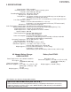
VL-A111U/AH131U VL-AH151U/AH161U 2. SPECIFICATIONS Signal System: Recording System: Cassette: Recording/Playback Time: Tape Speed: Pickup Device: Lens: Lens Filter Diameter: Monitor: Microphone: Color Temperature Compensation: Minimum Illumination: Video Output Level: Audio Output Level: Speaker Output: Power Requirement: Power Consumption: Operating Temperature: Operating Humidity: Storage Temperature: Dimensions (approx.): Weight (approx.
Speaker Microphone 6 Cassette compartment door Lens hood Lithium battery holder Shoulder strap loop DC IN jack AUDIO/VIDEO jack Terminal cover Cassette compartment door release Cassette holder When the cassette compartment door is open Zoom lens Front view DISPLAY button Operation buttons Tripod socket Battery compartment door release Power switch (CAMERA/VCR select switch) Hand strap FADE button Shoulder strap loop Power Zoom Wide angle/ Telephoto control VOLume control RECord START
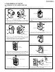
VL-A111U/AH131U VL-AH151U/AH161U 4. DISASSEMBLY OF THE SET 4-1. REMOVAL OF THE CAMERA SECTION Note: Before removing the cabinet, turn off the power supply, and ascertain that the battery has been removed. (b) Connector (b) Pull out (a) (1) Camera front cabinet (d) (a) 5. Remove the connector of the 6-cell detection switch, and remove two screws ((b)LX-HZ0018TAFF) fixing the battery catcher. 1.
VL-A111U/AH131U VL-AH151U/AH161U 4-2. DISASSEMBLY OF THE VCR MAIN BODY <1. Removal of the VCR lid shaft> Area A (b) (k) (2) Remove five screws ((b)LX-HZ0018TAFF). (1) Remove one screw ((k)LX-HZ0063TAFN).
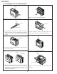
VL-A111U/AH131U VL-AH151U/AH161U <3. Removal of the VCR lid> Caution for installation of the VCR lid Microphone connector VCR lid Area B When installing the VCR lid, move the VCR lid in the arrow direction, keeping the VCR lid parallel to the main body as shown above. (1) Disconnect the microphone connector. <4.
VL-A111U/AH131U VL-AH151U/AH161U <8. Removal of the Lithium PWB> (b) LCD unit Lithium PWB Main PWB Connector Connector Inverter transformer (3) Remove two screws ((b)LX-HZ0018TAFF) and two connec- (1) Remove the connector of the Lithium PWB from the Main PWB. tors, and remove the LCD unit (with inverter) from the main (2) Move the lithium unit in the direction of the arrow. body. <9. Disassembly of the frame V> <6.
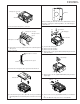
VL-A111U/AH131U VL-AH151U/AH161U Claw C Claw B View E Claw A Claw D View F Note: When fixing the cassette compartment lid, first engage the claws A and B, and then engage the claws C and D, confirm that the four claws (A, B, C and D) of the cassette compartment lid are securely engaged as shown in the view above. <11.
VL-A111U/AH131U VL-AH151U/AH161U 4-3. REPLACEMENT OF CCD SENSOR 4-3-1. BEFORE REPLACEMENT 1) The CCD image sensor is more sensitive to electrostatic breakage than C-MOS LSI. Therefore sufficient means to prevent electrostatic damage must be taken when it is replaced. • Ground the soldering iron. • Ground also the human body, using the wrist strap(through an 1 Mohm resistor). • Until the CCD sensor is mounted on the PWB, fit it to the conductive sponge, and short-circuit the foot lead.
VL-A111U/AH131U VL-AH151U/AH161U 5. MECHANISM ADJUSTMENT 5-1. MECHANISM CHECKING/ADJUSTING JIGS, TOOLS AND PARTS 5-1-1. Mechanism checking/adjusting jigs and tools 1. Cassette torquemeter for PB 2. JiG8T-012 3. CV * (10 g·cm/25 g·cm) 1. Cassette torquemeter for VS-REW 2. JiG8T-032 3. CV * (50 g·cm/25 g·cm) 1. Torque gauge 2. JiGTG0045 3. CN * For measurement of loading brake torque Configuration 1. Name 2. Part No. 3. Code * Model, Application 1. Torque gauge head 1.
VL-A111U/AH131U VL-AH151U/AH161U 5-2. ITEMS AND TIMINGS OF INSPECTION AND MAINTENANCE The mechanism of VCR needs the following periodic inspection and maintenance in order that it maintains its high quality. Also, after the machine is repaired, execute the following maintenance and checks regardless of how long it has been used. 5-2-1. Inspection and maintenance list Checking/Maintenance point 500 Used time (hrs.
VL-A111U/AH131U VL-AH151U/AH161U 5-3. MECHANISM CHECKS AND ADJUSTMENTS The description given below relates to the general field services, but does not relate to the adjustment and replacement that require high level equipment, jigs, and technical skills. In order to maintain the initial characteristics of the machine, it is necessary to execute the maintenance and check and to prevent damage to tapes and other parts. For adjustments which need jigs, be sure to use the jigs.
VL-A111U/AH131U VL-AH151U/AH161U 5-3-4. Checking and adjusting the tension pole position (1) Check When it begins to wind the P6-120 tape check whether the tension pole is in the specified position to the Si roller as shown in the figure. If it is not in the specified position, remove the cassette and adjust the position in the following procedure. (2) Adjustment 1. Don’t set up any tape, and select the PB mode. (Refer to Item 5-5-1-(4).) 2.
VL-A111U/AH131U VL-AH151U/AH161U 5-4. ADJUSTMENT OF MECHANISM TAPE RUNNING SYSTEM Sup tilted pole 5-4-1. Preparation for adjustment Sup GR (1) Clean the tape running areas (guide poles, rollers, drum, Capstan shaft, Pinch roller) (Figure 1) Si roller (2) Connect the oscilloscope to the following TPs. RF output ..... TL7410 H-SW-P ....... TL7417 GND ............. TL7413 (3) Playback the alignment tape (VR2ABOPS). Tension pole (4) Ascertain that each guide is free from remarkable curl.
VL-A111U/AH131U VL-AH151U/AH161U 5-4-4. Adjusting the Tu guide Height setting jig Master plane (JiGMP-MX7U) Upper flange After replacement of Tu guide preset and adjust the height. (1) Tu guide height presetting (Figure 6) Adjust the height from the upper surface of mechanism chassis to the upper surface of lower flange with the aid of jig. Lower flange Figure 6 (2) Adjusting the Tu guide (Figure 7) 1 Playback the alignment tape (VR2ABOPS).
VL-A111U/AH131U VL-AH151U/AH161U 5-5. MECHANISM ASSEMBLING AND PARTS REPLACEMENT (DISASSEMBLING AND ASSEMBLING) Below is given an explanation of assembling of mechanism and its parts replacement. The removal of cabinet and the PWB is explained in the relevant service manual. Notes 1 After removal of cut washers be sure to replace them with new ones. 2 Do not place the mechanism upside down on the table. Otherwise, the mechanism part may be deformed or damaged, resulting in malfunction.
VL-A111U/AH131U VL-AH151U/AH161U 5-5-2. Cassette control ass’y Lock Lever (1) Set the unit to the EJECT mode, and let the housing stand upright. Or set the unit to the STANDBY mode, press the lock lever in the arrow direction, and let the housing stand upright. (See Fig. 5: in the direction a or b ) (When pushing in the direction a , slightly lift the housing by hand to release the lock lever.) (2) Remove the four screws 2 and take out the down guide 3.
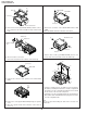
VL-A111U/AH131U VL-AH151U/AH161U 5-5-5. Phase matching The phase of the following parts must be matched as shown in the figure below. (Ascertain that the marks and round holes align.) (1) Lo relay gear (3) Sub-cam (2) Main cam (4) Mode switch Lo relay gear Phase matching mark (Round hole) Mode switch Phase matching mark ( Mark) Phase matching mark (Round hole) 5-6. MECHANISM ASSEMBLING METHOD (1) Adjust the phase of each part. (2) Install screws and washers.
VL-A111U/AH131U VL-AH151U/AH161U (7) Install the guide rail assembly taking care to position it (4) Install the loading block assembly and the capstan motor. correctly. (5) Install the drive gear. At this time, pay attention to the direction of gear. (The small gear must be located in the B A chassis side.) a a A a Make sure not to deform the arm. Loading motor Capstan motor a A a D C Move FF downwards Install the motor under this plate. Drive gear Position the smaller gear towards the chassis.
VL-A111U/AH131U VL-AH151U/AH161U (8) Install the drum assembly in the chassis. (9) Install the tape guide in the drum assembly. (10) Install the Si roller. (11) Install the slide chassis. T arm guide B Tape guide A Slide this part towards the T arm. Place the slide chassis on the guide rail. A Drum assembly B A A Si roller B Roller spring Main cam pin B Insert the main cam pin into the hole of cam of slide chassis. Sup reel base Item A M1.4 x 1.5 ø4.5 B M1.4 x 1.5 ø3.
VL-A111U/AH131U VL-AH151U/AH161U 6. ADJUSTMENT OF THE ELECTRICAL CIRCUITS 6-1. BEFORE ADJUSTMENT · Electric circuit adjustment becomes necessary, in most cases, when any of the wear mechanical parts or the video head has been replaced. Before starting the electric circuit adjustment, be sure to check that the mechanical parts work well (i.e., the mechanical parts have all been perfectly adjusted).
VL-A111U/AH131U VL-AH151U/AH161U 6-3-4. Setting value Table 3) When IC002 is replaced Table 1) When IC705 is replaced MODEL AH131U AH151U AH161U DATA DATA DATA 00 00 00 FF FF FF 01 01 01 FE FE FE 00 00 00 FF FF FF 00 00 00 FF FF FF 00 00 00 FF FF FF VTR ADJ A111U ADD. DATA 01 00 Model 09 FF 02 01 Destination 0A FE 03 60 Specification 0B 9F 04 00 Menu 1 0C FF 05 00 Menu 2 0D FF CAM DATA ADJ A111U AH151U ADD.
VL-A111U/AH131U VL-AH151U/AH161U 6-4. TEST mode TEST No. Title 1 Sensor Off 2 3 4 5 6 7 8 Mecha Adjustment mode Shut Off Adjustment Error Display PASS mode Cam Adjustment mode VCR Adjustment mode Head Switching Point ADJ. Contents All the sensors are off except for the cassette control switch, DEW sensor, and battery sensor. ATF sampling is restricted to the central part. Shutoff voltage value is written in E2PROM.
VL-A111U/AH131U VL-AH151U/AH161U 1 2 3 4 5 1. Extension Cable Inverter~VCR (7pin) 2. QCNW-1265TAZZ 3. AX 1. Extension Cable 1. Extension Cable 1. Extension Cable 1. Extension Cable LCD~ MECHA~VCR (70pin) Camera~VCR (20pin) Camera~VCR (24pin) VCR (24pin) 2. QCNW-1534TAZZ 2. QCNW-1774TAZZ 2. QCNW-1382TAZZ 2. QCNW-1382TAZZ 3. BS 3. BH 3. BD 3. BD 6 7 8 insulating sleeve 1. Operation Unit 2. QSW-Z0287TAZZ 3. AW 1. Battery Terminal Unit 1. AV Jack Unit 2. RUNTK0352TAZZ 2.
VL-A111U/AH131U VL-AH151U/AH161U 6-6-3. VCR circuit adjustment * Before adjusting the VCR circuit, make sure that the fixed value in 6-3-2 is written in E2PROM. · Test points on the video circuit board. 6-6-3-1. Supply voltage adjustment/check POWER CIRCUIT ADJUSTMENT PROCEDURE Turn on power û 1. Adjust to CAM 15V û 2. Check P-CON 4.9V û 3. Check P-CON 3.3V û 4. Check P-CON 3.1V û 5. Check DSP 2.65V û 6. Check DSP 1.85V û 7. Check LCD 13.2V û 8. Check LCD 7V û 9. Check LCD -15.2V û 10.
VL-A111U/AH131U VL-AH151U/AH161U 6-6-3-2. Head Switching Point Adjustment 1) Play back the alignment tape (JiGWR5-5NSP) Measuring instrument 2) Press the “CONTINUE” key and “TEST SEL.” key on the adjustment remote control to set the test mode. Mode (At this time the numeral of “T-01” blinks.) Adjustment address 3) Using the “FF” and “REW” keys, select “T-08”, and press Tape "PLAY" key to set the SW-P adjustment mode. 4) When the adjustment is completed, "HSWP" is displayed and the tape is ejected.
VL-A111U/AH131U VL-AH151U/AH161U 6-6-3-4. Adjustment of audio circuit 1. Adjustment of filter f0 Measuring instrument Oscilloscope Mode PB Input signal (tape) JiGWR5-5NSP Measuring terminal TL605/AUDIO.OUT Adjustment address 33 (VTR ADJ) Set value Clear the waveform 1) Set the alignment tape (JiGWR5-5NSP). 2) Using the adjustment remote control (RRMCG0033TASA), set the VCR adjustment mode, and set the address “33” with the operation switch ("FF", "REW" key). 3) Play back the standard tape.
VL-A111U/AH131U VL-AH151U/AH161U 5. VCO adjustment Measuring point Address(VTR ADJ) Mode Adjusting method TL3802 03E VCR 1) Connect TL3803 to GND. 2) Connect the frequency counter to TL3802, and adjust the frequency. Adjustment standard 15.734kHz ± 100Hz Remarks ——————— 6. H-position adjustment Measuring point TL3802 Address(VTR ADJ) 03B Mode VCR Adjusting method 1) Connect the oscilloscope to TL3802, and adjust the pulse width. t V Adjustment standard 3 type: 2.8µsec ±0.15µsec (A111U/AH131U/AH151U), 3.
VL-A111U/AH131U VL-AH151U/AH161U 6-7. CAM section adjustment 6-7-1. CAM section adjustment jigs (1) Object, measuring instrument and jigs necessary for camera section servicing • • • • • Gray scale chart Vectorscope Extension cable Oscilloscope Video output cable • Color bar chart • Color temperature conversion filter HOYA "LB-165" • Digital voltmeter • • • • Halogen light (2 pcs.) Color video monitor AC adapter Service Remote Control Configuration 1. Name 2. Part No. 3.
VL-A111U/AH131U VL-AH151U/AH161U 6-7-3. CAM circuit adjustment * Before adjusting the CAM circuit, make sure that the fixed value in 6-3-3 is written in E2PROM. 6-7-3-1. Supply voltage check Check that the voltages at the following TL are within the specified range (refer to the supply voltage adjustment/check under VCR circuit adjustment). Measuring point TL0137 TL0138 TL0140 Item P-CON_4.9V P-CON_3.1V P-CON_5.7V SPEC 4.9V 3.1V 5.
VL-A111U/AH131U VL-AH151U/AH161U 6-7-3-6. Black balance, AF noise level adjustment Mode CAM ADJ Measuring instrument — Subject Not specified Measuring point — Adjustment address 71 Adjustment reference 01 1) Write ADD:71 DATA:01. 2) Press the “STOP” key to reconfirm ADD “71”. Adjustment is completed when “FF” is returned to DATA. 6-7-3-7.
VL-A111U/AH131U VL-AH151U/AH161U 6-8. TROUBLE SHOOTING 6-8-1. Classification of troubles No operation at all Check the Power circuit and system control circuit. û YES Check the system control and loading motor circuit. û YES Check the inverter transformer and power circuit. û YES * Check the DSP circuit. û YES Check the DSP circuit, RF circuit and head amplifier circuit. û YES Check the DSP circuit, RF circuit and head amplifier circuit.
VL-A111U/AH131U VL-AH151U/AH161U 6-8-2. Troubleshooting for the camera section û YES Check the lens drive circuit (IC551) and main signal line. û YES Check IC401 (DSP), and its peripherals. û YES Check IC706 System Control, IC551 (Lens driver) and their peripherals. û YES Check IC706 System Control, IC551 (Lens driver) and their peripherals. û YES Check IC706 System Control, IC551 (Lens driver) and their peripherals.
VL-A111U/AH131U VL-AH151U/AH161U 7. BLOCK DIAGRAMS 7-1. SYSTEM BLOCK DIAGRAM BATTERY NONREGE IC701 IC900 POWER (CAMERA) 3.0V Reg Power Control IC POWER (SYS 3.0V) POWER (AT 3.
6, 7 36 5 1 IC101 BUFFER Q1403 BUFFER 24 22 20 LCD_VR LCD_VG LCD_VB 8 IC800 BUFFER LPF 6 C-FILTER Y-FILTER CDS AGC / ACC CDS_AGC Q1404/Q1406 CCD9CK CCD14CK PANEL IC1451 BUFFER AMP 25, 26 3, 5, 17, 18 V-DRIVER 13 CCD_OUT 4 Q1 VIDEO DRIVER Q2407 HPF Q2405 LPF VIDEO-OUT Q2401 NOISE CANCEL BLOCK ATT LIMITER 27 10 IC11 CCD SENSOR TIMING GENERATOR 40, 42 Q2402/Q2403 IC12 LENS SY-IN SC-IN 8 LPF 7 LPF 8 BUFFER Q1401 BUFFER Q1402 V_SIGNAL 39 IC151 C
6, 7 36 5 1 IC101 BUFFER 24 22 20 LCD_VR LCD_VG LCD_VB 8 IC800 BUFFER LPF 6 C-FILTER Y-FILTER CDS AGC / ACC BUFFER Q1403 ACC_AMP CDS_AGC Q1404/Q1406 CCD9CK CCD14CK PANEL IC1451 BUFFER AMP 25, 26 3, 5, 17, 18 V-DRIVER 13 CCD_OUT 4 Q1 VIDEO DRIVER Q2407 HPF Q2405 LPF VIDEO-OUT Q2401 NOISE CANCEL BLOCK ATT LIMITER 27 10 IC11 CCD SENSOR TIMING GENERATOR 40, 42 Q2402/Q2403 IC12 LENS SY-IN SC-IN 8 LPF 7 LPF 8 BUFFER Q1401 BUFFER Q1402 V_SIGNAL 39
6, 7 36 5 1 IC101 BUFFER Q1403 BUFFER 24 22 20 LCD_VR LCD_VG LCD_VB 8 IC800 BUFFER LPF 6 C-FILTER Y-FILTER CDS AGC / ACC CDS_AGC Q1404/Q1406 CCD9CK CCD14CK PANEL IC1451 BUFFER AMP 25, 26 3, 5, 17, 18 V-DRIVER 13 CCD_OUT VIDEO DRIVER Q2407 10 IC11 HPF Q2405 LPF VIDEO-OUT Q2401 NOISE CANCEL BLOCK ATT LIMITER 27 TIMING GENERATOR 40, 42 Q2402/Q2403 IC12 LENS 4 Q1 8 LPF 7 LPF 8 BUFFER Q1401 BUFFER Q1402 V_SIGNAL 39 A/D Converter C_OUT Y_OUT B_OUT
6, 7 36 5 1 IC101 BUFFER Q1403 BUFFER 24 22 20 LCD_VR LCD_VG LCD_VB 8 IC800 BUFFER LPF 6 C-FILTER Y-FILTER CDS AGC / ACC CDS_AGC Q1404/Q1406 CCD9CK CCD14CK PANEL IC1451 BUFFER AMP 25, 26 3, 5, 17, 18 V-DRIVER 13 CCD_OUT 4 Q1 VIDEO DRIVER Q2407 HPF Q2405 LPF VIDEO-OUT Q2401 NOISE CANCEL BLOCK ATT LIMITER 27 10 IC11 CCD SENSOR TIMING GENERATOR 40, 42 Q2402/Q2403 IC12 LENS SY-IN SC-IN 8 LPF 7 LPF 8 BUFFER Q1401 BUFFER Q1402 V_SIGNAL 39 IC151 C
6, 7 36 5 1 IC101 BUFFER Q1403 BUFFER 24 22 20 LCD_VR LCD_VG LCD_VB 8 IC800 BUFFER LPF 6 C-FILTER Y-FILTER CDS AGC / ACC CDS_AGC Q1404/Q1406 CCD9CK CCD14CK PANEL IC1451 BUFFER AMP 25, 26 3, 5, 17, 18 V-DRIVER 13 CCD_OUT 4 Q1 VIDEO DRIVER Q2407 10 IC11 HPF Q2405 LPF VIDEO-OUT Q2401 NOISE CANCEL BLOCK ATT LIMITER 27 TIMING GENERATOR 40, 42 Q2402/Q2403 IC12 LENS CCD SENSOR SY-IN SC-IN 8 LPF 7 LPF 8 BUFFER Q1401 BUFFER Q1402 V_SIGNAL 39 IC151 C
CH4 output Drive circuit (Rise and fall voltage) CH5 output Drive circuit (Voltage drop) CH4 ERROR AMP. IN- Comparator section CH5 ERROR AMP. IN- Comparator section 3 4 43 8 Standard power CH8 ERROR AMP. IN- Comparator section IN+ B/L CTL CH7 ERROR AMP. IN- Comparator section IN+ 7 CAP ERROR 6 DRUM ERROR CH8 output Drive circuit (NPN) CH7 output Drive circuit (Rise and fall voltage) CH6 output Drive circuit (Voltage drop) CH3 output Drive circuit (Rise and fall voltage) CH3 ERROR AMP.
LED Green DC JACK input 44 LED_R LED_G LED Red Charging : Red light up Completion : Green light up with JACK : OPEN with out JACK : GND Short circuit VDC<8V Voltage detective circuit 1 SW1 EXT Vcc 2 SW2 Charge control IC 7 8 Q2901 CS 5 3 LV 4 GND MM1332G CEL 6 ADP-DET Q2903 NON REG T PRE-CHARGE-ON CHARGE-ON_H Ni-MH battery BATT.-DET Q2903 with FET is always "OFF" at DC input.
VL-A111U/AH131U VL-AH151U/AH161U 7-5. LENS DRIVE BLOCK DIAGRAM IC1 CCD SENSOR ZOOM LENS MASTER LENS IC101 CDS AGC IC151 A/D IC401 DSP 42 41 DATA 49 48 IC706 LENS DATA2 CS 2 12 SYSTEM CONTROL DATA CLK 3 IRIS, FOCUS, ZOOM CONTROL 4 124 MASTER LENS POSI 21 IRIS METER IC553 4.
VL-A111U/AH131U VL-AH151U/AH161U 8. SCHEMATIC DIAGRAMS 8-1.
VL-A111U/AH131U VL-AH151U/AH161U 8-2.
VL-A111U/AH131U VL-AH151U/AH161U 8-3.
VL-A111U/AH131U VL-AH151U/AH161U 8-4.
VL-A111U/AH131U VL-AH151U/AH161U 8-4.
VL-A111U/AH131U VL-AH151U/AH161U 8-5.
VL-A111U/AH131U VL-AH151U/AH161U 8-6.
VL-A111U/AH131U VL-AH151U/AH161U 8-6.
VL-A111U/AH131U VL-AH151U/AH161U 8-7.
VL-A111U/AH131U VL-AH151U/AH161U 8-8.
VL-A111U/AH131U VL-AH151U/AH161U 8-9.
VL-A111U/AH131U VL-AH151U/AH161U 8-10.
VL-A111U/AH131U VL-AH151U/AH161U 8-11.
VL-A111U/AH131U VL-AH151U/AH161U 8-12.
VL-A111U/AH131U VL-AH151U/AH161U 8-12.
VL-A111U/AH131U VL-AH151U/AH161U 8-13.
VL-A111U/AH131U VL-AH151U/AH161U 8-13.
VL-A111U/AH131U VL-AH151U/AH161U 8-14.
VL-A111U/AH131U VL-AH151U/AH161U 8-15.
VL-A111U/AH131U VL-AH151U/AH161U 8-16.
VL-A111U/AH131U VL-AH151U/AH161U 8-17.
VL-A111U/AH131U VL-AH151U/AH161U 8-18.
VL-A111U/AH131U VL-AH151U/AH161U 8-19.
VL-A111U/AH131U VL-AH151U/AH161U 9.
VL-A111U/AH131U VL-AH151U/AH161U VCR PWB Wiring Side SIDE A J I H G F E D C B A 1 2 3 4 5 6 93 7 8 9 10
VL-A111U/AH131U VL-AH151U/AH161U VCR PWB Component Side SIDE B J I Q2905 D901 C907 Q907 D900 D2913 D903 FB151 C916 C920 Q911 C943 R151 SC151 C1929 R1942 C164 R196 TL176 R174TL175 TL178 R173TL177 R186 R175 R177TL179 TL187 R178TL180 TL181 TL188 R179 R180TL182 R182 TL184 R183 R3842 R3838R3847 TL3801 TL185 TL1801 R930 TH3800 TL915 R931 C946 C952 IC904 R3806 R3805 C3818 R3853 C3819 C3817 C3815 Q3801 R3851 R3852 R3846 Q3800 TL3805 R729 R713 R728 R712 R727 R711 R726
VL-A111U/AH131U VL-AH151U/AH161U VCR PWB Wiring Side SIDE B J I H G F E D C B A 1 2 3 4 5 6 95 7 8 9 10
VL-A111U/AH131U VL-AH151U/AH161U CAMERA PWB Component Side SIDE A J TL26 L101 I P101 SC101 TL19 R12 C12 R27 R22 Q11 R19 C17 Q12 C25 TL14 TL12 TL25 R34 C29 L12 L551 C565 Q14 C37 TL561 TL562 TL563 TL564 TL551 TL552 TL553 TL554 TL555 TL556 TL558 TL557 R124 TL124 Q551 R146 R145 R143 R137 R135 R132 R126 TL115 TL114 TL113 TL112 R123 TL111 R131 R127 TL129 R129 E R128 TL122 R133 TL30 TL121 R142 R134 TL31 R139 R138 C563 SC551 L553 C38 C35 C34 TL101 TL100 C11 L
VL-A111U/AH131U VL-AH151U/AH161U CAMERA PWB Wiring Side SIDE A J I H G F E D C B A 1 2 3 4 5 6 97 7 8 9 10
VL-A111U/AH131U VL-AH151U/AH161U CAMERA PWB Component Side SIDE B J C104 I C120 C119 Z2 C15 C13 C14 R102 R101 TL102 C103 C105 R105 C107 R104 R103 H C115 R100 IC11 C101 R107 R106 C102 R108 C109 C114 TL136 C112 C116 C110 R150 C16 IC101 IC102 R151 C106 R148 P102 TL135 R147 R555 R551 TL571 TL572 C560 C551 R552 R557 G C568 TL149TL148 IC552 R122 TL150 C552 R111 TL147 TL143 TL142 R553 FB110 TL137 TL138 R561 R576 R564 C575 R578 C570 R556 R117 C554 R55
VL-A111U/AH131U VL-AH151U/AH161U CAMERA PWB Wiring Side SIDE B J I H G F E D C B A 1 2 3 4 5 6 99 7 8 9 10
VL-A111U/AH131U VL-AH151U/AH161U HEAD AMP PWB Component Side SIDE A C3707 C3708 J R3731 R3718 R3730 TL3752 R3715 R3716 C3705 TL3721 TL3722 C3710 C3712 C3717 IC3701 R3722 R3720 C3719 C3721 C3718 R3721 C3722 TL3707 TL3703 C3716 C3715 C3702 C3703 TL3708 TL3704 R3703 R3701 R3705 R3707 R3702 R3704 C3704 C3706 R3733 C3701 R3732 R3706 R3708 C3713 C3714 C3711 I R3717 C3709 TL3705 C3720 TL3732 C3723 C3727 C3725 H R3723 TL3702 C3728 TL3733 C3726 L3701 L3702 R3719 TL3
VL-A111U/AH131U VL-AH151U/AH161U HEAD AMP PWB Wiring Side SIDE A J I H G F E D C B A 1 2 3 4 5 6 101 7 8 9 10
VL-A111U/AH131U VL-AH151U/AH161U HEAD AMP PWB Wiring Side SIDE B J I H G F E D C B A 1 2 3 4 5 6 102 7 8 9 10
VL-A111U/AH131U VL-AH151U/AH161U Part No. ★ Description LIST/ Code 10. REPLACEMENT PARTS EXPLODED VIEWS Ref. No. Ref. No. Parts marked with " å " are important for maintaining the safety of the set. Be sure to replace these parts with specified ones for maintaining the safety and performance of the set. " HOW TO ORDER REPLACEMENT PARTS" Contact your nearest SHARP Parts Distributor.
VL-A111U/AH131U VL-AH151U/AH161U Ref. No. Part No.
VL-A111U/AH131U VL-AH151U/AH161U Ref. No. ★ Part No.
VL-A111U/AH131U VL-AH151U/AH161U Ref. No. Part No.
VL-A111U/AH131U VL-AH151U/AH161U Ref. No. Part No.
VL-A111U/AH131U VL-AH151U/AH161U Ref. No. Part No.
VL-A111U/AH131U VL-AH151U/AH161U Ref. No. R1404 R1407 R1408 R1409 R1410 R1411 R1413 R1416 R1452 R1453 R1454 R1455 R1458 R1803 R1806 R1807 R1808 R1809 R1810 R1812 R1813 R1814 R1815 R1816 R1817 R1818 R1819 R1820 R1821 R1901 R1902 R1903 R1905 R1906 R1907 R1908 R1909 R1910 R1911 R1912 R1913 R1914 R1915 R1916 R1917 R1919 R1920 R1921 R1922 R1923 R1924 R1925 R1926 R1927 R1929 R1930 R1931 R1932 R1933 R1934 R1935 R1936 R1937 R1938 R1939 R1940 R1941 R1942 R1943 R1944 R1945 R1946 R1947 R1948 R1949 Part No.
VL-A111U/AH131U VL-AH151U/AH161U Ref. No. Part No.
VL-A111U/AH131U VL-AH151U/AH161U Ref. No. R8463 R8464 R8467 R9410 ★ Part No.
VL-A111U/AH131U VL-AH151U/AH161U Ref. No. ★ Part No.
VL-A111U/AH131U VL-AH151U/AH161U Ref. No. C3716 C3717 C3718 C3719 C3720 C3721 C3722 C3723 C3724 C3725 C3726 C3727 C3728 C3729 C3730 C3731 C3732 C3733 C3734 ★ Part No. VCKYCZ1AB104K VCKYCY1AF105Z VCKYCZ1AB104K VCKYCZ1EB682K VCKYCZ1AB104K VCKYCZ1EB682K VCKYCZ1EB682K VCKYCY1AB474K VCKYCY1AB474K VCKYCY1AF105Z VCKYCY1AB474K VCCCCZ1HH101J VCCCCZ1HH101J VCKYCZ1CB103K VCKYCZ1AB473K VCKYCZ1EB472K VCKYCZ1AB104K VCSATA1CJ106M VCSATA1CJ106M Description 0.1 1 0.1 6800p 0.1 6800p 6800p 0.47 0.47 1 0.47 100p 100p 0.
VL-A111U/AH131U VL-AH151U/AH161U Ref. No. Part No. ★ Description Ref. No.
VL-A111U/AH131U VL-AH151U/AH161U ★ Ref. No. Part No.
VL-A111U/AH131U VL-AH151U/AH161U Ref. No. Part No. ★ Description Ref. No.
VL-A111U/AH131U VL-AH151U/AH161U MECHANISM Ref. No. Part CHASSIS No. ★ EXPLODED Description VIEW Code Ref. No. ★ Part No.
VL-A111U/AH131U VL-AH151U/AH161U Ref. No. Part No. ★ VIEWDescription CABINET EXPLODED Ref. No. Code 3-2 k ★ Part No.
VL-A111U/AH131U VL-AH151U/AH161U Ref. No. Ref. No. Part No. ★ CONTROL Description Code CASSETTE HOUSING UNIT EXPLODED VIEW Part No. ★ Description Code 400 401 C 401 B A 1 2 3 4 5 6 CAMERA UNIT EXPLODED VIEW 5 D 6 2 4 3 C 1 The imprint must be on the face. B CCD side Lens side Imprint Face the thinner part toward the lens side.
VL-A111U/AH131U VL-AH151U/AH161U Ref. No. Part No. ★ Description 11. PACKING OF THE SET Ref. No. Code Part No. ★ Description Code No.1 No.12 No.21 No.13 No.7 No.18 No.8 No.5, No.14 No.17 No.23 No.9 No.19 No.2 No.11 No.6 No.4 No.20 No.3 No.22 No.10 No.16 No.15 ACCESSORIES No. 1 Model A111U/AH131U/ AH151U/AH161U ACCESSORIES (NOT REPLACEMENT ITEM) Parts Code Description No.
VL-A111U/AH131U VL-AH151U/AH161U Ref. No. Part No. ★ Description Ref. No. Code 121 Part No.
VL-A111U/AH131U VL-AH151U/AH161U Ref. No. Part No. ★ Description Ref. No. Code ★ Part No. Description Code COPYRIGHT C 2002 BY SHARP CORPORATION ALL RIGHTS RESERVED. No part of this publication may be reproduced, stored in a retrieval system, or transmitted in any form or by any means, electronic, mechanical, photocopying, recording, or otherwise, without prior written permission of the publisher.