
Service manual


7
VL-A111U/AH131U
VL-AH151U/AH161U
4. DISASSEMBLY OF THE SET
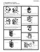
4-1. REMOVAL OF THE CAMERA SECTION
Note:
Before removing the cabinet, turn off the power supply, and ascertain that the battery has been removed.
Pull out
Lens connector
(d)
(b)
Pull out
(a)
(a)
(1)
Camera front cabinet
1. Remove one screw ((d)XiPSF20P04000), one screw ((b)LX-
HZ0018TAFF), two screws ((a)LX-HZ0018TAFN), and pull
out the camera front cabinet (1).
CCD
connector
(c)
Lens holder
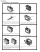
4. Pulling the lens holder, pull out the lens upwards. Then,
remove the lens connector.
(b)
Connector
(c)
Connector
2. Remove one screw ((b)LX-HZ0018TAFF), one screw
((d)XiPSF20P04000) and two screws ((a)LX-HZ0018TAFN)
and pull out the camera rear cabinet (2) backwards.
Remove the FPC in the camera rear cabinet.
(b)
(d)
Connector
(a)
(a)
Pull out
(2)
Camera rear cabinet
1
2
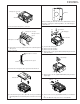
6. Remove two screws ((b)LX-HZ0018TAFF) and pull out the
camera side cover from the tilt frame C.
Tilt frame C
(b)
(b)
Pull out
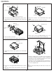
9. After removing the camera PWB from the tilt frame C, remove
the connector on the rear of the PWB.
Connector
8. Remove one connector of the camera PWB, and remove two
screws ((c)LX-HZ0045TAFN) fixing the PWB.
7. Remove the battery catcher from the camera side cover.
3. Firstly, remove the CCD connector from the Camera PWB, then
remove one screw ((c)LX-HZ0045TAFN), on the reverse side in
this figure (do not remove the lens holder in this section).
5. Remove the connector of the 6-cell detection switch, and
remove two screws ((b)LX-HZ0018TAFF) fixing the battery
catcher.
FPC
Ferrite
PSPAH0031TAZZ