
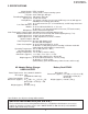
Service manual


9
VL-A111U/AH131U
VL-AH151U/AH161U
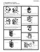
<3. Removal of the VCR lid>
Microphone wire spacer
Microphone connector
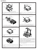
Caution for installation of the VCR lid
<Detail of area B>
<Detail of area B>
Microphone connector
Microphone connector
Microphone wire
spacer
VCR Lid
VCR lid
(2) Remove the connector cable from the hole of the microphone
wire spacer.
(1) Disconnect the microphone connector.
(3) Remove the microphone wire spacer from the Frame V.
Wire fixing tape
(4) Pull out the microphone wire cable with care to prevent it from
interfering with the mechanical parts, and remove the VCR
lid.
Pull out
Area B
Microphone connector
AV unit wire
AV unit FPC
(b)
(b)
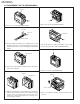
<4. Removal of the AV unit and AV unit cover>
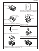
<5. Disassembly of the LCD holder>
Tripod angle
(b)
(b)
(b)
(1) Peel the wire fixing tape.
(2) Remove the AV unit wire.
(3) Remove the AV unit FPC.
(4) Remove two screws ((b)LX-HZ0018TAFF) fixing the AV unit
and LCD holder.
(d)
(d)
(1) Remove three screws ((d)XiPSF20P04000) and pull out the
tripod angle.
(2) Remove three screws ((b)LX-HZ0018TAFF) on the tilt frame
V.
Move the tilt frame V by a looseness of the tilt FPC.
(d)
When installing the VCR lid, move the VCR lid in the arrow
direction, keeping the VCR lid parallel to the main body as
shown above.
Frame V