
Service manual


9
VL-AX1U
6.
7.
8.
9.
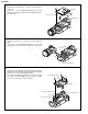
• Remove the 1 screw ((Q)XiPSN17P02000) and 5 screws
((O)XiPSF17P03000), and pull out the VF unit in the direc-
tion of the arrow.
• Remove the 1 screw ((N)XiPSF17P02000) to detach the
battery cover.
• Remove the 3 screws ((B)LX-BZ0232TAFD) and 1 screw
((C)LX-BZ0245TAFF).
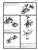
• Open the cassette lid, and pull out the mechanism through the
opening in the direction of the arrow.
• Remove the 1 screw ((I)LX-HZ0050TAFN), and pull out the
lens cabinet in the direction of the arrow.
• Remove the 2 screws ((K)LX-HZ0063TAFN) and 1 screw
((O)XiPSF17P03000) to detach the tilt cover.
• Remove the 2 screws ((F)LX-HZ0017TAFF) to detach the
LCD cabinet.
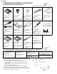
• Turn the LCD tilt to verticalize it to the LCD cabinet.
• Remove the 2 screws ((O)XiPSF17P03000) and 2 screws
((R)XiPSN17P03000).
Battery cover
VF unit
(O)
(O)
(O)
(N)
(Q)
Mechanism
Head-amp=Main FPC
(B)
(B)
(B)
(C)
Lens cabinet
(l)
*Hole direction caution
Tilt cover
LCD cabinet
LCD tilt
(F)
(F)
(O)
(K)
(K)
(O)
(O)
(R)
(R)