
Service manual


VL-H870U
VL-H875U
VL-H890U
VL-H870U
VL-H875U
VL-H890U
4-1
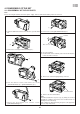
4. DISASSEMBLY OF THE SET
4-1. DISASSEMBLY OF THE VCR PARTS
Note:
Before removing the cabinet, turn off the power supply, and ascertain that the battery has been removed.
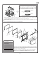
(4) Remove the A.V.terminal cover and the screws
(i)XiPSN20P04000(3pcs.).
<1. Removal of the Cabinet L>
A.V.terminal FPC
(9) Remove the A.V.terminal FPC.
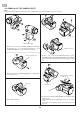
Note:
The FPCs and the wires of process (7), (8), and (9) are connect-
ing with the L.Cabinet, and remove the L.Cabinet while it is
floating from the main body.
If the L.Cabinet is drawed violently, they have some apprehen-
sions of snap off the wires.
(8) Remove the outside charging battery connector.
(6) Close the VCR lid.
(7) Lift about half of the L.Cabinet parts in the arrow direction,
remove the FPC connector.
L.Cabinet
FPC connector
(5) Remove the screws(i)XiPSN20P04000(2pcs.).
(1) Slide the VCR lid knob in the arrow direction, open the VCR
lid.
(b)
(2) Remove the screws(b)LX-HZ0018TAFF(2pcs.).
(i)
(d)
(3) Turn the Camera section, and remove the screws
(i)XiPSN20P04000(1pc.), (d)XiPSF20P04000(1pc.).
(i)
(i)