VL-FD1U VL-FD1U VL-E990E SERVICE MANUAL S50A2VL-FD1U/ LIQUID CRYSTAL DIGITAL CAMCORDER SERVICE MANUAL MODEL NTSC VL-FD1U LIQUID CRYSTAL DIGITAL CAMCORDER In the interests of user-safety (Required by safety regulations in some countries) the set should be restored to its original condition and only parts identical to those specified be used. CONTENTS NTSC MODEL VL-FD1U Page 1. IMPORTANT SERVICE NOTES .................................................................................................
VL-FD1U VL-E990E 1. IMPORTANT SERVICE NOTES connections, metal cabinet, screw heads, knobs and control shafts, etc.) and measure the AC voltage drop across the resistor. Reverse the AC plug (a non polarized adaptor plug must be used but only for the purpose of completing these checks) on the set and repeat the AC voltage measurements for each exposed metallic part. Any reading of 0.45V rms (this corresponds to 0.3mA rms AC.
VL-FD1U VL-E990E WARNING :TO REDUCE THE RISK OF FIRE OR ELECTRIC SHOCK, DO NOT EXPOSE THIS APPLIANCE TO WET LOCATIONS. CAUTION CAUTION RISK OF ELECTRIC SHOCK DO NOT OPEN This symbol mark means following. Camcorder only For continued protection against fire hazard, replace only with same type fuse. (CP901; 1.25A 24V, CP902; 1.25A 24V, CP903; 1.25A 24V) CAUTION: TO REDUCE THE RISK OF ELECTRIC SHOCK. DO NOT REMOVE COVER. NO USER·SERVICEABLE PARTS INSIDE. REFER SERVICING TO QUALIFIED SERVICE PERSONNEL.
VL-FD1U VL-E990E CAUTION BEFORE BATTERY DESTROY NICKEL-CADMIUM BATTERY The following program is available in the United States. Please consult local environmental authorities concerning the availability of this or other programs in your area. The RBRCTM Seal SHARP participates in the RBRCTM* Nickel-Cadmium Battery Recycling Program in the United States.
VL-FD1U VL-E990E 2. SPECIFICATIONS Signal System: Recording System: Cassette: Recording/Playback Time: Tape Speed: Pickup Device: Lens: Lens Filter Diameter: Monitor: Microphone: Color Temperature Compensation: Minimum Illumination: Video Output Level: Audio Output Level: Speaker Output: Power Requirement: Power Consumption: Operating Temperature: Operating Humidity: Storage Temperature: Dimensions (approx.): Weight (approx.
VL-FD1U VL-E990E 3. PART NAMES AND FUNCTION For details on the use of each control.
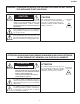
VL-FD1U VL-E990E 4. DISASSEMBLY OF THE SET Note: Before removing the cabinet, turn off the power supply, and ascertain that the battery has been removed. 1. (f) 5. (f) (f) (c) • Remove the screws ((f)LX-BZ0224TAFC)(1 pc.) and ((c)XiPSC17P04000)(4 pcs.) fixing the camera front cabinet and camera side cover. • Open the LCD section and remove the screws ((f)LXBZ0224TAFC)(2 pcs.). 2. 6. (g) (f) (f) • Remove the screws ((f)LX-BZ0224TAFC)(2 pcs.) fixing the camera front cabinet.
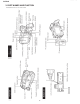
VL-FD1U VL-E990E 9. 13. (e) (c) (e) (c) (c) (c) (e) • Remove the screws ((e)XiPSF17P02000)(2 pcs.) fixing the camera frame coupling metal and the screws ((e)XiPSF17P02000)(2 pcs.) fixing the camera frame C to detach the camera section. • Remove the screws ((c)XiPSC17P04000)(4 pcs.) fixing the camera lower cabinet. (e) 10. 14. (p) (p) (f) (f) • Remove the screws ((f)LX-BZ0224TAFC)(2 pcs.) fixing the camera frame and the screw ((e)XiPSF17P02000)(1 pc.) fixing the camera frame C.
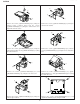
VL-FD1U VL-E990E 17. (r) (r) (r) (k) (b)XiPSC17P03000 M1.7×3 Silver Small Screw (c)XiPSC17P04000 M1.7×4 Silver Small Screw (d)XiPSC17P05000 M1.7×5 Silver Small Screw (e)XiPSF17P02000 M1.7×2 Black Small Screw (f)LX-BZ0224TAFC M1.7×2.5 Chrome (g)LX-BZ0222TAFF M1.7×3 Black (h)LX-BZ0221TAFC M1.7×3 Chrome (k)LX-BZ0231TAFE Floating Screw (n)XiPSF20P04000 M2×4 Black Small Screw (p)LX-HZ0050TAFF M1.7×4 Black P Tight • Remove the floating screw ((k)LX-BZ0231TAFE)(1 pc.
VL-FD1U 5. MECHANISM ADJUSTMENT JIGS AND PARTS 5-1. Mechanism check adjustment jigs 1. PB-use cassette Torque meter 2. 9DASD-1015 3. DB * SD-1015 1. Torque gauge 2. JiGTG0045 3. CN * For use in VS-REW winding torque measurement. 1. Torque gauge head 2. 9EQTGH-DH5000 3. BW * For use with the above torque gauge. 1. Tension gauge 4N 2. JiGSG0400 3. BK * For measurement of pinch roller pressure. Configuration 1. Name 2. Part No. 3. Code * Model, Uses Remarks 1.
VL-FD1U 6. INSPECTION AND MAINTENANCE ITEMS AND INTERVALS In order to keep the mechanical section always in good condition, perform the following inspection and maintenance at regular intervals. In addition, after repair, perform the following maintenance items regardless of how long the user has been using the unit. 6-1. List of inspection and maintenance items Tape running system Inspection and maintenance location 500 Tape running section (see section 8-3) • • • • • • • Check.
VL-FD1U 7. MECHANICAL ADJUSTMENTS AND CHECKS The items discussed here relate to general on-site servicing (field servicing). Adjustments and replacements that require sophisticated facilities, jigs and technology are omitted. In addition, in order to maintain the characteristics that the unit has when it is new, not only are inspection and maintenance necessary, but it is absolutely necessary that, for example, the tape not be damaged, and always use jigs for adjustments that require them.
VL-FD1U 7-4. Back tension torque check and adjustment in record (playback) mode AC adapter used, with cassette controller assembly (1) Checking Set the torque cassette (SD-1015), and make sure in the SP record mode that the supply side torque is within the standard shown below (or in the playback mode for the tape on which the signal has been SP-recorded). (If torque ripple exists, read its center value.) 0.7 ± 0.1mN·m (2) Adjustment (Fig.
VL-FD1U (If the tension fluctuates, read its center value.) 15 ± 12mN 7-8. Checking of winding Tu reel base ratchet torque DC3V, without cassette controller assembly (Independent Mechanism) (1) Remove the cassette controller assembly, then apply DC3V to the loading motor and put the system into standby mode. (refer to 9-1) (2) Move the swing arm toward the S reel base side. Be careful not to cause damage to the gears and other parts in the process. (Fig.
VL-FD1U 8. TAPE RUNNING ADJUSTMENT 8-1. Adjustment locations · T roller, arm · Tu guide, arm · Slide chassis · S guide · Pole base · Guide roller · Drum assembly · Capstan motor, etc. Adjust the height of only replaced parts with the adjusting jig.
VL-FD1U 8-4. Running rough adjustment (Since this adjustment is performed without cassette controller, put a proper weight so that the cassette does not rise , and make an adjustment.) 1) Su, Tu guide roller height adjustment Entrance side NG (1) Loosen the guide roller lock screw, then tighten loosely so that the roller turns easily. (2) Replay an alignment tape, and adjust the Sup, Tu guide roller so that the envelope sides of entrance and exit are flat.
VL-FD1U 9. MECHANICAL SECTION ASSEMBLY AND PARTS REPLACEMENT (DISASSEMBLY AND REASSEMBLY) Mechanical section disassembly and reassembly are explained in this section. For removal of the cabinet, etc., refer to 4. DISASSEMBLY OF THE SET. 1. Always replace cut washers that have been removed, for example in parts replacement, with new ones. 2. When reassembling, be careful not to allow screws, washers or foreign matter to enter. They can cause mechanical misoperation. 3.
VL-FD1U (6) STOP mode (5) PLAYBACK (RECORD, FF, VSF) mode The system is in the STOP (Rec Lock in CAMERA mode) The mechanism position for playback, record, FF and fast position; the S and the T pole bases are snap-fitted to the drum feed playback. base, the S brake is in contact with the S reel base, and the Tu The pinch roller is pressed to the capstan axis, and the S/Tu brake is in contact with the Tu reel base. main brake is separated from the S/Tu reel base.
VL-FD1U 9-3. How to operate with the circuit board without the cassette controller assembly. In this method, if the procedure is followed incorrectly there is danger of damaging the mechanism and the tape, so except in special cases, such as when measuring the VSR torque, do not perform this procedure. Normally operate this unit with the cassette controller assembly attached. Be sure to follow each caution mentioned. (1) Apply DC3V to the loading motor to set the EJECT mode.
VL-FD1U 9-5. Reassembly 9-5-1. Reassembly in side of the main chassis. Note) Numbers before part names are given as a guide to the order of assembly. As for greasing/oiling/cleaning places refer to the attached drawings (Grease/Oil application Fig. 1, 2). 1. 4.
VL-FD1U 7. Guide roller assembly 454 9. (3) Dew FPC cover P 325 S pole base assembly 451 Tu pole base assembly 452 378 (2) Down switch attachment angle sub assembly G SL chassis holder S Solder-joint A G S loading arm assembly Positioning 307 Grease Guide rail 362 F Positioning 395 Tu loading arm assembly 308 F S pressure spring 396 372 Tu pressure spring S loading gear 373 F G Item Tightening torque Quantity CWø0.7-ø2.2-t0.25 2 Special screw · 5mN·m 2 M1.2 x L1.
VL-FD1U 382 (6) T roller upper flange 455 (6) T roller Ass'y 384 (6) T roller inner (6) F T arm SPR. 392 382 (2) T roller upper flange 383 (6) T roller bottom flange 381 (2) Tu pole 397 (6) Guide adjustment SPR. (9) S guide hexagon nut 428 (5) L (7) C 354 (7) Tension band Ass'y 393 Grease (1) Tu guide arm SPR. 394 (3) Pinch lever return SPR.
VL-FD1U GREASE/OIL APPLICATION From rear surface side From rear surface side 304 Main cam 303 Pinch control lever 307 S loading arm 312 Intermediate gear angle O : Oiling G : Greasing Including groove side surface (Rear surface · groove side surface) Fig. 1.
VL-SD20U VL-FD1U 10. ADJUSTING THE ELECTRICAL CIRCUITS Before starting the electric circuit adjustment • The adjustment methods described herein are used, in most cases, when the expendable mechanical parts, including the video head, have been replaced, at which time the electrical circuits need to be readjusted. Before adjusting the electrical circuits, make sure that the mechanism works properly (i.e., the mechanism is properly adjusted).
VL-FD1U VL-SD20U ■ ID code is acquired 1. Connect with the EUI48/64 ID code control system. (1) Start the Internet Explorer or Netscape Navigator. (2) Access the following address. (URL:http://www.rcg.kami.sharp.co.jp/quics/e_index.html) Select the "EUI48/64 ID code control system" from the "Service" item. Note: If you want to establish a connection by directly inputting the URL, please input the following. URL:http://www1.rcg.kami.sharp.co.jp:7000/adrs_agt/adrs_dba/ide00010.
VL-SD20U VL-FD1U (6) Input the necessary information for the application. For the indispensable input items, be sure to input them. Select the [Group/company] and [Kind name] from the list. Input the [Model name]. Input the [Serial number]. Input the [Site/department of repair]. For the input items when making each application, refer to the "Input item list for the ID acquisition application". (7) Click on [motion]. The confirmation screen will appear. (8) Click on [Yes]. 5.
VL-FD1U VL-SD20U VL-FD1U Specifications of service jigs No.
VL-SD20U VL-FD1U [TEST POINT] (Wiring board diagram: Main Side A) (Wiring board diagram: Main Side B) C967 TL1907 C982 C993 C989 L921 TL616 R624 R626 TL2606 C631 BAT2601 S1501 C633 TL2627TL2629 TL2653 TL2615 TL2659 TL2613 TL2609 TL2660 SC2607 R651 R650 TL2614 C605 C651 R640 C646 TL2604 C650 SC2601 TL2638 P2604 C638 TL604 TL2656 TL2630 R656 TL2651 C637 TL2619 Q605 TL2631 TL2649 TL2628 TL2654 R662 R629 Q603 R655 L601 L602 TL2612 TL2611 TL2623 TL2621 R666 TL2636 TL
VL-FD1U VL-SD20U [Making adjustments] Adjusting the servo system controller and related parts 1. Setting the system codes Replacement of IC7702 (FLASH MEMORY) requires the following data to be set in this order. [Procedure] Set the unit to the VCR mode and set the data for each address. Code 1. Model code 2. Destination code Address 01 09 02 0A Data 00 FF 01 FE 3. Specifications 4. Menu selection code code 03 0B 04 0C 04 FB 00 FF 5. Software switching 6.
VL-SD20U VL-FD1U ADJUSTING THE ELECTROMAGNETIC CONVERSION CIRCUIT SYSTEM 1. PLL VCO adjustment Mode Procedure Examples VCR ADJ mode 1) Playback the alignment tape (or a self-recorded tape). 2) Call the adjustment mode (V-ADJ). 3) Set the address "2A" and call the data. 4) Set the called data with the FF/REW key to the point where the playback screen appears. (At this time, the screen full of block noise is OK.) • During E2PROM replacement. • During circuit board (Main) replacement. 2.
VL-FD1U VL-SD20U 2. PCO D/A-C adjustment Test point Procedure TL2407 Mode EE mode 1) Connect the AVS cable and then connect it to the monitor (TO). 2) Call the adjustment mode (V-ADJ). 3) Set the address to "23", and call the data. 4) Vary the data with the FF and REW keys to set the signal appearing at TL2407 to 0.64Vp-p ± 0.05. yyyyyy ,,,,,, ,,,,,, yyyyyy ,, yy ,,,,,, yyyyyy ,, yy ,,,,,, yyyyyy ,,yyyyyy yy ,,,,,, yyyyyy ,,,,,, 0.64±0.05 • During E2PROM replacement. • During IC4401 replacement.
VL-SD20U VL-FD1U 3. COM-Amplitude adjustment Test point Mode Procedure Adjustment rating Examples TL1801 Address VCR ADJ 29 CAM 1) Set TL1801 to GND. 2) Adjust the output voltage of TL1801 with the address 29 and the DC voltage with a digital voltmeter to the adjustment standard value. 6.55V ± 50mV 4.
VL-FD1U VL-SD20U ADJUSTING THE MIC AMP CIRCUIT TL601 EE level Frequency character (Wiring board diagram: Audio I/O Side B) TL605 EE level Frequency character FB602 BAT2602 TL2646 TL605 R688 R687 TL615 TL601 TL616 TL2658 R628 R669 TL2655 C620 C621 C619 TL2661TL617 FB601TL614C1501 FB603 R624 R626 R638 C631 C632 BAT2601 S1501 C633 Q605 R662 R629 C605 TL2627TL2629 TL2659 TL2653 R651 R650 TL2660 C650 R640 TL603 EE level Frequency character 1.
VL-SD20U VL-FD1U 10-2. Camera Section Adjustments 10-2-1. Camera section service (1) Camera adjustment is performed after the set has been completed. (2) Subjects, measuring instruments and jigs needed for camera section service and adjustments • • • • • • Gray scale chart Color bar chart Oscilloscope Digital voltmeter Vector scope Halogen lamp: 2 pcs. • • • • Frequency counter Illumination meter Color temperature meter Color temperature conversion filter HOYA "LB-165" 10-2-2.
VL-FD1U VL-SD20U 4) Operation flow FF or REW PLAY FF or REW PLAY STOP Address is selected and specified, with the data called. Then the called data are selected and fixed. The operation flows in this sequence. 5) When the adjustment is complete: Press the "CONTINUE" key to let the "CAM ADJ" display disappear from the screen.
VL-SD20U VL-FD1U 2) Shifting to the normal operation mode Set the data for the address "0000" to " FF". ] This shifts the mode to the normal operation mode. ] Press the "CONTINUE" key, and the "CAM ADJ" display goes out of the screen, enabling the normal operation. (5) Camera unit adjustment procedure 1. Auto focus adjustment 6. Color gain coarse adjustment 2. Iris basic adjustment 7. White balance adjustment 3. Black balance adjustment/A/F noise adjustment 8. Color gain adjustment 4.
VL-FD1U VL-SD20U 10-2-4. Adjustment procedures Adjustment method Item (1) Auto-focus adjustment Set the unit to the auto-focus function adjustment mode and write data to the address "09FD" one after another. This executed the adjustments automatically. The items to be adjusted are as listed below. Every time an adjustment is made properly, the data "FF" is written to the address. After each adjustment, make sure that the adjustment has been made properly, and then go on to the next adjustment item.
VL-SD20U VL-FD1U Adjustment method Item (4) Iris AE adjustment (1) Video output is observed with the oscilloscope in the grey scale standard record state, • Measurement terminal: the data of address "0002" is rewritten, and the luminance signal level (not including S terminal luminance signal output sync signal) is adjusted to 700 ± 10mVp-p.
VL-FD1U VL-SD20U Adjustment method Item (7) White balance adjustment • Measurement terminal: EE output • Address: "0050" INDOOR W/BR "0052" INDOOR W/BR • Measuring instrument: Vector scope • Object: Grey scale • Data variation width: "0000" to "03FF" (1) White balance adjustment is performed repeatedly.
VL-SD20U VL-FD1U 11. USEFUL TIPS (PROBLEMS DIFFER FROM THOSE FOUND ON VHS OR 8MM DECKS BECAUSE THE SIGNALS ARE DIGITALLY PROCESSED.) Camera (EE mode) Picture fails to appear Camera (REC mode) VCR (PB mode) VCR (EE mode) Picture fails to appear when tape recorded on this unit or another unit is played back. (EE OK) Blueback fails to appear.
VL-FD1U 12. SIGNAL FLOW DIAGRAMS 12-1.
VL-FD1U WAVEFORM DIAGRAM (DURING COLOR BAR PLAYBACK) 12-3.
VL-FD1U 12-5. FLOW IN PB MODE (AUDIO) WAVEFORM DIAGRAM (1.
IC101 CDS/AGC D/A Con. REC (EE) IC1001 E2PROM PB IC552, 553 IRIS DRIVE 54.000MHz IC11 TG V-Driver IC1 380K CCD-Sensor IC501 16Bit LENS MICON IC551 LENS DRIVER Lens Camera section IC151 10Bit A/D Video out IC1401 ANALOG VIDEO I/O IC202 16Mbit SDRAM CameraZoom IC201 CAMERA ENGINE (Total ASIC) CAM DSP PC M-CTL ZOOM IC701 SUPER I/O OSD Synthesis PPW v1 LCD CTL PPW LCD IC4401 VIO ENGINE (Total ASIC) VCR/LCD Section CLK Gen.
OFD V1, V2, V3 H1, H2, RS IC1 CCD-Sensor VHiiCX216AY IC11 TG / V-Driver VHiCXD2478R-1 48P FSX, FCDX, BCPX, PBLK 45 CAM-HEAD X11 54.
J2401 CAMERA SECTION BLOCK DIAGRAM CAM ENGINE 46 SEP Y IN/OUT SEP C IN/OUT VIDEO IN/OUT SEP-Y-IN VIDEO-IN IC1431 VHiNJM2235V-1 ZYP0~7 ZCP0~7 ZUVSELP ZCLKP ZHDP ZVDP A-C-IN IC1401 VIDEO I/O VHiNJM2538B-1 20P A-Y-OUT A-C-OUT A-Y/COMP-V-IN IC4401 VIO ENGINE RH-iX0707TAZZ 304P CDY0~7, CDC0~7 REC (EE), PB PB REC (EE) CLD, SPD, CTR EX1, EX2, EX3 SPS, RES, CLS, LOW C OUT FRPV R OUT G OUT B OUT SINID, INTID, FLDID CVDR, CHDR CLK135VCX0 I/O SEL SC800 COM VR, VG, VB IC2800 LCD INTERFACE VHi
DI00~15 47 REC (EE), PB PB REC (EE) XCS, XWE, XRAS, XCAS, XUDQM, XLDQM, XCKE, CK18MIV SM-ADR0~11 CVDR CHDR I/OSEL SINID, INTID, FLDID CDUVSELP CDHDP, CDVDP IC407 Codec External Memory RH-iX0793TAZZ 50P IC4401 VIO ENGINE RH-iX0707TAZZ 304P CDY0~7 CDC0~7 LINK FP IC7401 RH-iX0749TAZZ IEEE1394 120P CLK8.192 ID0~7 IC452 REC/PB ENGINE RH-iX0710TAN1 328P ICRCE, ILWRE IDIR, ICLK, IV X401 24.
REC (EE), PB PB REC (EE) REC/PB ENGINE BLOCK DODAT PDAD PDDA ADMCK CMODE DFSO DFSI AIDAT LINK FP ICRCE, ILWRE IDIR, ICLK ID0~7 CLK 8.192 AUD-R AD IN AUD-L AD IN AUD-R DA OUT AUD-L DA OUT IC1602 16bit ADC/DAC VHiPCM3006T 24P IC7401 IEEE1394 RH-iX0749TAZZ 120P TPA, TPA-, TPB, TPB- J7401 DV CONNECT IC601 AUDIO I/O VHiBH7761KV 48P SUPER I/O HP OUT SP OUT AUDIO-R I/O AUDIO-L I/O CS, RD, WR IntMIC HP JACK SPEAKER AV JACK VL-FD1U 13-5.
M M LENS UNIT M IC1 CCD Sensor 49 Focus-Motor Drive-Sense Zoom-Motor Drive-Sense IC551 IC552,553 Iris Drive Sensor CF501 20M Lens µ-COM IC501 CAMERA HEAD X11 54.000MHz IC11 Timing Generator V-Driver IC101 CDS AGC A/D-Drive D/A-CON. AIO S1501 GYRO-Sensor IC1501 GYRO-AMP. IC151 10bit A/D-Converter I/O SSG Digital Auto C-Process Y-Process MAIN Electric Zoom Image Stabilizer Digital Noise Reduction IC201 Sirial Data Control Data Bus PB Y/C Data REC & PB Y/C Data VL-FD1U 13-6.
VL-FD1U 14. SCHEMATIC DIAGRAMS 14-1.
VL-FD1U 14-2.
VL-FD1U 14-3.
VL-FD1U 14-4.
VL-FD1U 14-5.
VL-FD1U å AND SHADED COMPONENTS=SAFETY RELATED PARTS 14-6.
VL-FD1U 14-7.
VL-FD1U 14-8.
VL-FD1U 14-9.
VL-FD1U 14-10.
VL-FD1U 14-11.
VL-FD1U 14-12.
VL-FD1U 14-13.
VL-FD1U 14-14.
VL-FD1U 14-15.
VL-FD1U 14-16.
VL-FD1U 14-17.
VL-FD1U 14-18.
VL-FD1U 14-19.
VL-FD1U 14-20.
VL-FD1U 14-21.
VL-FD1U 14-22.
VL-FD1U 14-23.
VL-FD1U 14-24.
VL-FD1U 14-25.
VL-FD1U 14-26.
VL-FD1U 14-27.
VL-FD1U 14-28.
VL-FD1U 15.
VL-FD1U 93 81 73 61 51 41 37 33 29 25 19 A 138 120 108 90 75 60 54 48 42 36 27 C EX0161TA EX0210TA EX0870CE HVU362 KV1812K MA729 MA2S111 F1J2H HVU350B HVU359TR F02J9 28 37 43 49 55 61 76 91 109 121 139 IX0616TA 64 44 38 30 28 24 20 16 14 10 32 22 19 15 14 12 10 8 7 5 NJM2904V IX0468TA Z4C2973G TC74VUC244FS IX0613TA 47 41 37 31 26 21 19 17 15 13 10 9 12 14 16 18 20 25 30 36 40 46 1 ADS933Y IX0474TA IX0422TA MB3825A IX0469TA BH7268KV IX0605TA IX0606TA IX0607TA MB3825A MB3785V 1 CXA2096N MS5483
VL-FD1U 16.
VL-FD1U MAIN PWB Wiring Side SIDE A J I H G F E D C B A 1 2 3 4 5 6 109 7 8 9 10
VL-FD1U MAIN PWB Component Side SIDE B J C967 Q920 C981 C151 C152 C993 C989 L921 SC900 R3477 CP1 C3421 C3423 R3437C3431 C3480C3481 Z1 SC2401 IC3405 R2404 TL6733 R2405 R2401 TL2403 TL6732 FB2406 R2407 C2401 R3474R3475 R2402 C3462 TL3324 R7403 FB2408 C3405C3409C3411 C3420 R3441 R3442 FL3402 R3465 R3458 R3497 R3498 R3496R3459R3464 R3489 C3442 C3443 SC3301 TL3303 TL3314 TL3343 TL3310 TL3345 TL3411 FB7401 Q3405 TL3308 R3460R3494 TL3307 R3495R3466R3467 C1726 R1712 R1711 Q3406
VL-FD1U MAIN PWB Wiring Side SIDE B J I H G F E D C B A 1 2 3 4 5 6 111 7 8 9 10
VL-FD1U CAMERA HEAD PWB C3 Component Side SIDE A J C4 TL7 TL9 TL12TL11 TL2 TL4 TL6 R5 Q2 Q1 C6 R4 R6 TL1 TL3 TL5 TL13 TL8 C5 C2 I C10 R2 C1 C1001 C8 D1 C7 IC1001 R1 R3 C9 TL10 H Q501 R519 R526 R525 R518 Q502 C114 SC501 Q504 R521 R515 R517 C506 Q503 R520 R527 L501 C501 C508 R524 C504 R512 C116 C112 C103 C113 C117 IC101 C507 C107 C119 C101 R507 C102 R108 C108 P101 R505 C104 L101 C118 R107 R523 R513 R502 R501 IC504 R511 R516 R514 C558 C559 IC501 R510 R
VL-FD1U CAMERA HEAD PWB Component Side SIDE B J IC1 I R12 R18 H R17 R11 C11 R15 R20 C23 R13 C22 TL502 TL519TL523 C12 C15 R23 R24 TL505 TL517 TL504 TL529 TL526 TL534 TL535 C20 C29 TL101 R104 X11 C28 TL539 TL501 TL516 TL531 TL533 TL524 TL530 TL522 TL521 TL570 TL571 TL537 TL536 TL538 R105 TL554 TL553 C18 TL541 TL525 L12 C32 TL102 R31 C33 TL540 R32 TL518 C27 C14 TL513 TL552 TL556 TL555 TL569 TL568 TL565 TL558 TL564 TL559 TL557TL572TL563 C25 C26 R113 R112 Q11 R114 TL509 TL5
VL-FD1U AUDIO I/O PWB Component Side SIDE A C616 C603 R672 R623 R625 R675 R674 L603 C642 R667 C660 R668 C626 C647 C625 R621 R634 C628 R653 R652 Q608 C623 C640 R685 R686 C624 C629 R614 R661 R645 R660 C617 C606 Q604 R616 Q606 IC601 R639 C1505 R641 C686 SC2602 C685 IC1501 R1502 R1503 R1501 C1502 C1504 C635 R603 C1507 R1506 C1506 C1503 R1504 G R676 R630 C643 R683 R1508 C1508 Q1501 R1509 R1505 R1507 R1510 C622 R627 IC1502 L1501 R1511 H C649 C636 FL601 C618 IC602
VL-FD1U AUDIO I/O PWB Component Side SIDE B J FB602 BAT2602 TL2646 TL605 R688 R687 TL615 TL601 I TL616 TL2658 TL2655 C620 C621 C619 TL2635 TL2633 TL2657 TL2661TL617 FB601TL614C1501 FB603 TL2634 Z2 TL2632 R624 R626 R638 TL2606 C631 C632 BAT2601 S1501 C633 C609 TL2628 TL2654 TL2615 TL2613 TL2659 TL2653 TL2609 R651 R650 C646 TL2638 TL2627TL2629 TL2660 TL2604 C650 R640 TL2647 TL2648 TL604 TL2656 TL2630 R656 TL2651 C637 P2604 SC2607 TL2644 C651 SC2601 C645 TL2645 C638
VL-FD1U LCD PWB J C9810 TL8810 TL8808 TL8804 TL8802 TL8801 TL8809 TL8806 TL8800 T9800 C9804 TL8828 TL8826 TL8823 TL8821 TL8819 TL8827 TL8824 TL8822 TL8820 TL8818 Q9801 L9801 C9806 C9807 Component Side SIDE A L9800 R3813 TL8834 SC8804 TL8853 R9809 R9808 R9805 R9806 FB9800 TH9800 IC9800 TL8845 SC8801 TL8847 SC8803 TL8858 C9803 R9804 R9803 D9800 TL8859 TL8835 TL8829 TL8830 TL8831 TL8862 TL8850 TL8849 TL8848 TL8844 TL8843 TL8842 C9811 TL8813 Q9803 C9809 TL9805 TL9801 C9808 R9807
D 1 C304 2 R304 C301 C313 C302 C306 C305 C340 E TL302 IC301 C321 C344 C318 C314 C312 C343 C309 L301 R380 C329 3 SC304 C342 R318 Q302 R312 R317 C311 C319 R314 R323 R325 C333 Q303 C327 R324 C332 R377 C324 R315 C323 C326 C322 C331 C330 R311 SC303 SC302 P306 H R320 R319 C307 R316 R313 C310 R308 R310 C308 R309 R321 F C320 C315 R331 R333 I SC305 IC302 R332 R330 VL-FD1U HEAD AMP PWB J Component Side Wiring Side SC301 TL303 G TL301 C345 C C303 C325 B SC306 A 4 5 6 117
VL-FD1U -MEMO- 118
VL-FD1U VL-SD20U Part No. ★ Description LIST/ Code 17. REPLACEMENT PARTS EXPLODED VIEWS Ref. No. Ref. No. ELECTRICAL PARTS LIST Parts marked with " å " are important for maintaining the safety of the set. Be sure to replace these parts with specified ones for maintaining the safety and performance of the set. Les pièces marquéss " å " sont importantes pour maintenir la sècurité de l'appareil.
VL-FD1U Ref. No. VL-SD20U ★ Part No.
VL-FD1U VL-SD20U ★ Ref. No. Part No.
VL-FD1U Ref. No. C988 C989 C990 C991 C992 C993 C1402 C1404 C1405 C1406 C1407 C1408 C1409 C1410 C1411 C1412 C1413 C1414 C1415 C1416 C1417 C1418 C1431 C1432 C1433 C1434 C1435 C1436 C1437 C1438 C1439 C1440 C1441 C1601 C1602 C1603 C1604 C1605 C1606 C1607 C1608 C1609 C1610 C1611 C1612 C1613 C1614 C1615 C1616 C1617 C1702 C1703 C1704 C1706 C1707 C1708 C1709 C1710 C1711 C1712 C1713 C1714 C1715 C1716 C1717 C1718 C1719 C1720 C1721 C1722 C1723 C1724 C1725 C1726 C1727 VL-SD20U Part No.
VL-FD1U VL-SD20U Ref. No. C3462 C3465 C3466 C3467 C3470 C3471 C3473 C3474 C3475 C3476 C3477 C3478 C3479 C3481 C4401 C4402 C4403 C4404 C4405 C4406 C4407 C4410 C4411 C4412 C4417 C4419 C4420 C4421 C4422 C4423 C4424 C4430 C4433 C4437 C4443 C4444 C4448 C4449 C4451 C4454 C4461 C4462 C4463 C4464 C4465 C4466 C4472 C4473 C4481 C4482 C4483 C4485 C4701 C4702 C7402 C7403 C7405 C7407 C7413 C7414 C7416 C7417 C7419 C7421 C7425 C7426 C7701 C7702 C7704 C7705 C7706 C7707 C7708 C7709 C7710 Part No.
VL-FD1U Ref. No. VL-SD20U Part No.
VL-FD1U VL-SD20U Ref. No. Part No.
VL-FD1U Ref. No. R3427 R3428 R3429 R3432 R3434 R3435 R3436 R3437 R3442 R3443 R3445 R3446 R3449 R3450 R3451 R3452 R3453 R3454 R3455 R3457 R3458 R3459 R3460 R3462 R3463 R3464 R3465 R3466 R3467 R3468 R3469 R3470 R3471 R3472 R3473 R3474 R3475 R3478 R3479 R3480 R3481 R3482 R3486 R3488 R3489 R3490 R3494 R3495 R3496 R3497 R3498 R3499 R4401 R4402 R4403 R4404 R4405 R4406 R4407 R4408 R4409 R4410 R4411 R4412 R4413 R4414 R4415 R4416 R4420 R4421 R4422 R4423 R4424 R4425 R4431 VL-SD20U Part No.
VL-FD1U VL-SD20U Ref. No. R7450 R7472 R7701 R7702 R7705 R7707 R7708 R7709 R7711 R7712 R7713 R7714 R7800 R7801 R7802 R7803 R7804 R7805 R7806 R7807 R7808 R7809 R7810 R7811 R7812 R7813 R7814 R7827 R7841 R7843 R7846 R7847 R7850 R7851 R7852 R7853 R7854 R7855 R7856 R9924 R9951 R9952 R9953 R9954 R9956 R9957 R9959 R9960 R9961 R9962 R9963 R9964 R9965 R9966 R9967 R9968 R9969 R9973 R9975 R9977 R9978 R9979 R9980 R9981 R9982 R9983 R9984 R9985 R9986 R9987 R9988 R9990 R9991 R9992 Part No.
VL-FD1U Ref. No. VL-SD20U ★ Part No.
VL-FD1U VL-SD20U Ref. No. ★ Part No. Description Ref. No.
VL-FD1U Ref. No. VL-SD20U ★ Part No. Description Code Ref. No.
VL-FD1U VL-SD20U Ref. No. ★ Part No. Description Ref. No.
VL-FD1U Ref. No. VL-SD20U Part No.
VL-FD1U VL-SD20U Ref. No. Part No. ★ Description Ref. No.
VL-FD1U VL-SD20U Ref. No. Part No.
VL-FD1U VL-SD20U MECHANISM CHASSIS Ref. No. Part No. ★ EXPLODED Description VIEW Code Ref. No. ★ Part No.
VL-FD1U VL-SD20U CABINET EXPLODED Ref. No. Part No. ★ VIEWDescription Code Ref. No.
VL-FD1U VL-SD20U CASSETTE CONTROL VIEW Ref. No. Part No. ★ EXPLOOD Description Ref. No. Code ★ Part No.
VL-FD1U VL-SD20U VL-FD1U SERVICE JIG★SPECIFICATIONS Ref. No. Part No. Description Code 1-1. Adjusting jigs for checking the mechanism No. Name New part Ref. No. Part No.
VL-FD1U VL-SD20U 18. PACKING THE SET Ref. No. Part No.OF ★ Description Ref. No. Code Part No. ★ Description Code No.17 No.2 No.3 No.5 No.22 No.4 No.7 No.20 No.8 No.9 No.21 No.10 No.14 No.11 No.6 No.1 No.18 No.13 No.12 No.19 No.15 No.16 ACCESSORIES (NOT REPLACEMENT ITEM) ACCESSORIES No.
VL-FD1U VL-FD1U Ref. No. VL-SD20U Part No. ★ Description Code Ref. No. ★ Part No. Description Code COPYRIGHT C 2000 BY SHARP CORPORATION ALL RIGHTS RESERVED. No part of this publication may be reproduced, stored in a retrieval system, or transmitted in any form or by any means, electronic, mechanical, photocopying, recording, or otherwise, without prior written permission of the publisher.