
Service manual


VL-E990E
7
VL-FD1U
4. DISASSEMBLY OF THE SET
Note:
Before removing the cabinet, turn off the power supply, and ascertain that the battery has been removed.
(f)
(c)
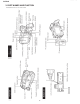
• Remove the screws ((f)LX-BZ0224TAFC)(1 pc.) and
((c)XiPSC17P04000)(4 pcs.) fixing the camera front cabinet
and camera side cover.
• Open the LCD section and remove the screws ((f)LX-
BZ0224TAFC)(2 pcs.).
(f)
(f)
(f)
(f)
(g)
• Remove the screws ((f)LX-BZ0224TAFC)(2 pcs.) fixing the
camera front cabinet.
• Remove the screws ((g)LX-BZ0222TAFF) fixing the battery
holder.
(f)
(d)
(d)
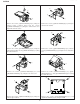
• Remove the screw ((f)LX-BZ0224TAFC)(1 pc.) fixing the cam-
era rear cabinet.
• Turn the camera and remove the screws ((d) XiPSC17P05000)
(2 pcs.).
Shielded wire
FPC
(f)
(f)
1. 5.
2. 6.
4. 8.
3. 7.
• Remove the screws ((f)LX-BZ0224TAFC)(2 pcs.) fixing the
camera rear cabinet.
• Remove the FPCs (2 pcs.) and shielded wire (1 pc.).