
Service manual


8
VL-Z1U
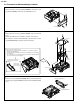
4. DISASSEMBLY OF THE SET
4-1. Procedure for disassembling the cabinet
Note:
Before removing the cabinet, turn OFF the power and make sure that the battery is not connected.
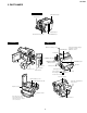
1.
· Remove the lens hood and remove the screw ((s) XiPSF14P06000).
· Open the LCD panel 90 degrees and remove the two screws ((x)LX-
HZ0050TAFN).
· Remove the two screws ((c)XiPSN17P04000) and remove the KS
camera front cover by pulling it frontward.
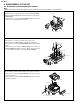
2.
· Disconnect the connector of the KS camera front cover.
· Disconnect the two LCD tilt FPCs of the liquid crystal panel.
· Remove the two screws ((r) XiPSN20P08000) and remove the LCD
panel.
· Remove the screw ((p) LX-HZ0063TAFN) and screw ((q)
XiPSN17P06000) that hold the camera L cabinet, open the terminal
cover and remove the three screws ((b) XiPSN17P03000).
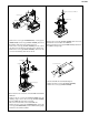
3.
· Disconnect the operation FPC and remove the camera L cabinet.
· Remove the screw ((c) XiPSN17P04000) and remove the KS
camera bottom cover.
· Remove the two screws ((a) XiPSN17P02000) and remove the LCD
tilt reinforcing fitting.
r
r
p
b
b
b
q
Camera L cabinet
Connector
LCD tilt FPC
KS camera front cover
Terminal cover
LCD panel
c
a
a
KS camera bottom cover
Camera L cabinet
LCD tilt reinforcing fitting
Operation FPC
s
c
c
x
x
LCD panel
KS camera front cover
Lens hood