Solutions for Demanding Applications VarTech Systems Inc. Industrial CRT and Flat Panel Displays VT19B-PW 19” Auto Sync Color Monitor User’s Guide Read these instructions completely before attempting to operate your new Color Display.
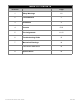
TABLE OF CONTENTS Sections Page 1 Safety Warnings 2 FCC Statement 3 3 Installation 4 4 Controls 5-10 5 Pin Assignments 11-12 6 Troubleshooting Guide 13 7 Mechanical Drawings 14 Panel Mount Mechanical 15 Specifications 16 8 19” Fast Scan Series User Guide 1-2 150-062
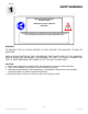
Section 1 SAFETY WARNINGS RISK OF ELECTRIC SHOCK! DO NOT OPEN!!! WARRANTY VOID IF CASING IS REMOVED. CAUTION: To reduce the risk of electric shock, do not remove cover (or back). No user serviceable parts inside. Refer servicing to qualified technician. WARNING TO PREVENT FIRE OR SHOCK HAZARD, DO NOT EXPOSE THIS MONITOR TO RAIN OR MOISTURE. “HIGH VOLTAGE EXISTS ON THE CATHODE-RAY TUBE ANODE LEAD OF THIS MONITOR. BEFORE SERVICING, DETERMINE THE PRESENCE OF HIGH VOLTAGE BY CONNECTING THE H.V.
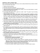
IMPORTANT SAFETY INSTRUCTIONS Prior to using this product, please ensure that you have carefully followed all the procedures outlined in the user’s manual for this product. 1. 2. 3. 4. Read all of these instructions. Save these instructions for later use. Follow all warnings and instructions marked on the product. Unplug this product from the wall outlet before cleaning. Do not use liquid cleaners or aerosol cleaners. Use a damp cloth for cleaning. 5. Do not use this product near water. 6.
Section 2 FCC STATEMENT FCC CLASS A STATEMENT The equipment has been tested and found to comply with the limits for a Class A digital device, pursuant to part 15 of FCC rules. These limits are designed to provide reasonable protection against harmful interference in a business installation. This equipment generates, uses and can radiate radio frequency energy and, if not installed and used in strict accordance with the instructions, may cause harmful interference to radio communications.
Section 3 INSTALLATION INSTALLATION 1.Be sure your cable(s) are attached to the respective graphics board. 2.Set the BNC/D-SUB Source for video input 3.Connect the AC power cable to a properly grounded outlet. 4.Boot your computer. Turn on the monitor power. The power LED indicator should be illuminated. If your monitor screen remains blank, check your video controller and computer system.
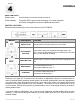
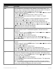
Section 4 CONTROLS USER CONTROLS Power button: Use this button to turn the monitor on and off. Power indicator: The power LED is green when the display is in normal operation. See Power management section for additional information. CONTROL LOCATION All controls are located on the rear of the monitor for the VT19B-PW. VarTech Button Description Function EXIT BUTTON Use this button to Exit the active menu or the OSD.
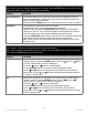
DIRECT-ACCESS FEATURE : This feature can be accessed quickly, at the touch of one button. When you finish making adjustments to a feature, push the EXIT button to turn off the menu or allow the OSD to time out and disappear automatically. Feature Function OSD Lock/Unlock This function allows you to secure the current control settings so that they cannot be inadvertently changed. You can unlock the OSD controls at any time by using the same procedure.
MENU FEATURES CONT. Feature Function Color Color temperature is a measure of the “warmth” of the image colors. The available range is between 5000 to 9300K. Follow these steps to change the color temperature and adjust individual R,G,B color control. 1. With the menu off, push the MENU button. Push the Õ or Ö button until the “Color” screen is displayed. 2. Use the × or Ø button to select Color1, Color2, or Color3. 3. Push the MENU button to open the “Color1”, “Color2”, or “Color3” adjustment screen. 4.
MENU FEATURES CONT. Feature Function Menu Position You can change the position where the OSD menu appears on your monitor. 1. With the menu off, push the MENU button. Push the Õ or Ö button until the “Menu” screen is displayed. 2. Push the × or Ø button to select Menu Position. 3. Push the MENU button to open the menu position adjustment screen. Use the Õ, Ö, × or Ø button to place the menu in the position you prefer.
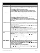
MENU FEATURES CONT. Feature Function Pincushion / Trapezoid Adjust the pincushion setting when the sides of the display are bowed in or bowed out; adjust the trapezoid setting when the top or bottom of the display is too large or small. 1. With the menu off, push the MENU button. Push the LEFT button or RIGHT button until the “Geometry” screen is displayed. 2. Push the UP button or DOWN button to select Pincushion/Trapezoid. 3. Push the MENU button to open the Pincushion/Trapezoid adjustment screen.
MENU FEATURES CONT. Feature Function Video Input Level Some video cards use video signals higher than 1.0V which causes the display to be very bright. For those video cards, use this feature to select the 1.0V Level. 1. With the menu off, push the MENU button. Push the Õ or Ö button until the “Advanced” screen is displayed. 2. Push the × or Ø button to select Video Input Level. 3. Push the MENU button to open the Video Input Level selection screen. Use the Õ or Ö button to select 0.7V or 1.0V.
Section PIN ASSIGNMENTS 5 HD15 Connector 15-Pin Connector (Figure 1) Pin No. Cable Adapter (Figure 2) Separate Composite Sync on Green Apple MacII 1 Red Red Red GND-R 2 Green Green Green+Sync Red 3 Blue Blue Blue H/V Sync. 4 GND GND GND Sense 0 5 DDC Return DDC Return DDC Return Green 6 GND-R GND-R GND-R GND-G 7 GND-G GND-G GND-G Sense 1 8 GND-B GND-B GND-B Reserved 9 Reserved Reserved Reserved Blue 10 GND-sync.
BNC CONNECTORS Pin Assignment SyncOn-Green Composite Sync. Separate Sync. R Red Red Red G Green+Sync. Green Green B Blue Blue Blue H/V NC H/V Comp. Sync. H-Sync. V NC NC V-Sync. *Note: Input Select Switch set to BNC TERMINATION SWITCHES For Normal Operation, have the RGB termination switches set to 75 OHM. For Loop-through Configuration set to HI Z position.
Section 6 TROUBLESHOOTING TROUBLESHOOTING The following list represents possible anomalies you may encounter with subsequent troubleshooting procedures. Please refer to this checklist prior to contacting a service representative. SYMPTOM WHAT TO CHECK There is no screen image 1. Power cord disconnected? 2. Power switch on? 3. Signal cable properly connected? “No Signal, Check Signal Cable” appears Check the signal cable connections between the computer and the monitor. “Out of Range” appears 1.
Section 8 SPECIFICATIONS ENGINEERING SPECIFICATIONS CRT Size 19” Video Bandwidth 250MHz dot clock Dot Pitch .20mm Active Display Area 13.85” x 10.39” / 351.79mm x 263.91mm Power Source 90-265VAC @50/60Hz Power Consumption 120 Watts maximum Scan Frequency Horizontal: 30 to 96kHz Vertical: 50 to 160Hz Video Bandwidth 250mHz Video Input Connectors 5BNC or HD15 Resolution Capabilities VGA to UXGA Video Input Signal Analog video 0.
VARTECH SYSTEMS INC. HEADQUARTERS 11529 Sun Belt Ct. Baton Rouge, Louisiana 70809 Toll-Free: 800.223.8050 International Phone: 001.225.298.0300 Fax: 225.297.2440 E-mail: sales@vartechsystems.com www.vartechsystems.com 19” Fast Scan Series User Guide 150-062-001 12.24.