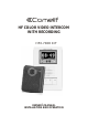
HF COLOR VIDEO INTERCOM WITH RECORDING HFX-700R KIT , OWNER S MANUAL INSTALLATION AND OPERATION
TABLE OF CONTENTS Section 1: User Article 1.Introduction 2.HFX-700R KIT 2.1.HFX-700R KIT Parts Identification 2.1.1.HFX-700R Main monitor identification 2.1.2.HFX-700R or EX-700D door camera identification 2.2.HFX-700R KIT Operation 2.2.1.Attention 2.2.2.On screen menu icons 2.2.3.Setup menu 2.2.3.1.Adjust clock 2.2.3.2.Door open status indication 2.2.3.3.Video or photo recording 2.2.3.4.Video display option during door release operation 2.2.3.5.Format a new SD card 2.2.3.6.Exit setup menu 2.2.4.
Section 2: Installation Article 16 1. System layout 19 2. Read before installation 20 3. HFX-700R installation 20 3.1.Examine package contents 20 3.2.Install main monitor 21 3.3.Install door camera 21 3.4.HFX-700R wiring and setting 22 3.5.Jumper function on main monitor 22 3.5.1.JP1, external doorbell trigger options 23 3.6.Jumper function on door camera 23 3.6.1.JP1, door control options and CCD on/off during the output 23 3.6.2.JP2, light senor options 24 4.
Section 1:User Article 1. Introduction Thank you for purchasing this Video Intercom System. This advanced system not only allows you to identify and communicate with visitors at the door and allows for remote door strike release, it can also record the video intercom communication on a micro SD card for later playback. This system has an interactive on screen menu for easy operation by touch sensitive buttons located on the two sides of the screen. Please read thru this manual for all detailed functions.
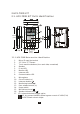
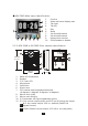
2.HFX-700R KIT 2.1. HFX-700R KIT Parts Identification 1 2 3 17 178mm (7.0 ) 15 14 7 8 36mm (1.42 ) 6 4 16 5 9 10 11 12 13 118mm (4.65 ) 2.1.1. HFX-700R Main monitor identification 1. Micro SD card slot socket 2. 3.5" Color TFT Screen 3. Touch sensitive buttons (4 on each side, unmarked) 4. Speaker 5. In use LED 6. Monitor LED 7. Intercom LED 8. Communication LED 9. Microphone 10. Cut-off button( ) 11. Intercom button( ) 12. Monitoring button( ) 13. Door release button( ) 14. Power switch 15.
HFX-700R Main menu identification: 1. 2. 3. 4. 5. 6. 7. 8. 9. 10. 1 2 4 3 5 6 7 8 9 10 Confirm Video and menu display area Tab right Tab left Play Setup 1st doorbell camera 2st doorbell camera Paging other monitor Chime enable or disable 2.1.2. HFX-700R or EX-700D Door camera identification 1 7 3 4 130mm (5.12") JP2 1 2 5 2 8 JP1 10 3 4 11 9 6 98mm (3.86") 36mm (1.42") 1. 2. 3. 4. 5. 6. 7.
2.2. HFX-700R KIT Operation 2.2.1. Attention A. Micro SD card, SDHC(High Capacity SD card), is not included in this product package. B. Insert SD card properly. The SD card can be 2GB to 16GB memory size. HC 4 i cro mS SD card socket C. The video quality is 720x480 pixels, every recording (20 sec. a section) takes about 15M memory size. Every photo takes about 130KB memory size (So for a 4 GB card, it can hold about 260 Videos or 25,000 pictures). D.
2.2.3. Setup menu A. Move cursor to SETUP icon at main menu; B. Press can enter setup menu. 2.2.3.1. Adjust clock A. At setup menu, and can move the cursor; can alter parameter (figure 1); B. can save your new setup. and 2.2.3.2. Door open status indication A. There are PT1 and PT2 terminals on main monitor for connection of a magnetic switch to detect door open status. (magnetic switch is not included in the package) B.
2.2.3.4. Video display option during door release operation A. At setup menu, and can move the cursor to the mode you like; to confirm. B. If select , when door is opening, video display is ON (figure 5). C. If select , when door is opening, video display is OFF (figure 6). DR Release Video ON 15:30 DR Release Video OFF VX.X.X(xxxxxx) 15:30 VX.X.X(xxxxxx) (figure 5) (figure 6) 2.2.3.5. Format a new SD card A. At setup menu, and can move the cursor to SD card format option; to confirm (figure 7). B.
2.2.4. Intercom function operations 2.2.4.1. Push to talk function(similar to walky-talky) A. Communication LED on means voice is free to go out from monitor to door camera. B. During the conversation, press the Monitor Button for 2 seconds to switch to push-to-talk mode.
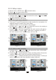
2.2.4.3. Zoom and pan/tilt function A. While talking to the doorbell camera from main monitor, tenant can at the same time operate the on-screen-menu to stop or resume video recording. B. To operate zoom and pan/tilt function has to stop recording first and resume afterward. (figure 9,10,11,12) REC 0 0 0 0 12 2010/06/28 04 57 39 SD X (figure 9:stop recording) SD 2010/06/28 04 57 39 X (figure 11 1 (figure 10 :resume recording) 2010/06/28 04 57 39 SD 3 X zoom) 3 (figure 12: pan/tilt) 2.2.4.4.
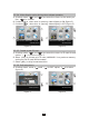
2.2.4.5. All page announcement and intercom among monitors A. From any monitor, tenant can press intercom button or select the function from the on-screen main monitor menu to page and make a nnoucements to other monitors (figure 13, 14). B. Paging and annoucements can last for 30 seconds time, if any other monitor press the intercom button to respond, the two monitors can then engage in intercom conversation for maximum of 90 seconds. SD 2010/06/28 04 5 7 39 (figure 13) (figure 14) 2.2.5.
10062800 /100401-1 1 01224 00 10/06/28 04 57 39 (figure 15) (figure 16) 2010/06/28 04 5 7 3 9 1 0 / 1 2/ 0 8 04 57 39 10120800 /1 1 2 6 5 5 - 1 (figure 17) (figure 18) 2.2.6.2. Delete video/photo section(s) A. Select to enter delete sub menu. (figure 19). B. Move and select delete by SINGLE video section or ALL video sections. C. Reconfirm YES or NO for the action (figure 20). D. Select EXIT to move to PLAYBACK menu; Select to return to main menu.
3. Expansion Video Monitor (EX-700H) 3.1. EX-700H Identification EX-700H 13 1 14 178mm (7.0 ) 12 5 6 36mm (1.42 ) 4 17 18 15 2 16 3 7 8 9 10 11 118mm (4.65 ) EX-700H identification: 1. 3.5" Color TFT Screen 2. Speaker 3. In use LED 4. Monitor LED 5. Intercom LED 6. Communication LED 7. Microphone 8. Cut-off button( ) 9. Intercom button( ) 10. Monitoring button( ) 11. Door release button( ) 12. Power switch 13. Brightness tuner( ) 14. Sharpness tuner( ) 15. Bell Volume tuner( ) 16.
3.2. EX-700H Operation 3.2.1. Visitor calls from door camera A. When the Call button on the camera is pressed, All monitors on the system will ring with a chime sound and all monitors will be activated. B. After the call, if nothing on the monitor is pressed, the system will time out after 30 seconds. If the monitor button is pressed, the system will stay active for 90 seconds. C. You are able to terminate the activity on the monitor at any time by pressing the Cut-off button . D.
4. Expansion Audio Monitor (EX-700A) 4.1. EX-700A Identification 14 178mm (7.0 ) 11 4 5 36mm (1.42 ) 3 12 1 13 2 6 7 8 9 10 118mm (4.65 ) EX-700A identification: 1. Speaker 2. In use LED 3. Monitor LED 4. Intercom LED 5. Communication LED 6. Microphone 7. Cut-off button( ) 8. Intercom button( ) 9. Monitoring button( ) 10. Door release button( ) 11. Power switch 12. Bell Volume tuner( ) 13. Speaker Volume tuner( ) 14.
4.2. EX-700A Operation A. Operates the same as the main monitor unit (Refer to page 12). B. EX-700A only audio function, not video function. 4.2.1.Broadcast and intercom function A. When system consists of main monitor and expansion audio monitor and an outdoor doorbell/camera unit, the system can provide intercom function. B. Press the intercom button from any monitor, all other monitors will react by making bell sound. At the same time, host can speak and broadcast voice message to all other monitors. C.
5. Optional video input converter (EX-VIN) 5.1. EX-VIN Identification 1 1. 2. 3. 2 3 Power LED The 2-wire terminals for connecting to the main monitor BNC connector for external camera video input 5.2. EX-VIN Operation A. EX-VIN converts video signal on the 2-wire transmission format of the system. B. Press the monitor button from any monitor to see the camera from the main door camera, press it again to scroll to the external camera device connected to the EX-VIN. C.
Section 2:Installation Article 1. System layout System layout 1: NOTE: the system is capable of expanding up to a total of 4 monitors (1 main video monitor + 3 expansion video monitors or 3 expansion audio monitors (any mix of video or audio) and 2 door cameras.
System layout 2: NOTE 1: The wiring HUB can amplify and distribute the 2-wire signal among the main monitor and sub-monitors. NOTE 2: the system is capable of expanding up to a total of 5 monitors with 1 EX-HUB or 8 total monitors with 2 EX-HUBs connected in one system.
A Max A Max HFX-700R EX-700D EX-700H or EX-700A B Max C Max EX-HUB OUT1 IN OUT2 POWER OUT3 POWER LED OUT4 EX-700H or EX-700A NOT E 1:OUT4 can also be used to connect to a expansion monitor. NOT E 2:wiring distance<300ft.
2. Read before installation Main monitor Proper height: Door camera View Angle: 70cm (27.6") 170cm (66.9") 100cm (39.3") 165cm (64.9") 50cm(19.7 ") 50cm(19.7 ") The proper height of monitor or door camera is 160~170cm(63"~67") from the ground. This may vary on each installation. View range should be actively tested before complete. Viewing window of door camera is about 70cm up-n-down, and 100cm left-n-right.
3. HFX-700R installation 3.1. Examine package contents NOTE: Examine the following contents of the package. PT1 PT2 DG1 HF COLOR VIDEO INTERCOM WITH RECORDING DG2 OUT + OUTDR2 DR1 <+ > P O WE R <-> X1 Wall mount bracket HFX-7 00R KI T X1 X1 Main monitor Door camera X1 Adaptor X4 , OWN E RS MA N UA L IN ST AL LA TION AN D OP E RAT ION Manual X4 White wall mount screws Flat head screws X1 X1 security screw wrench 3.2. Install main monitor A.
3.3. Install door camera A. Open the hidden latch, and unscrew to remove door camera unit from bracket. B. Fasten wall mount bracket to the surface where the unit will be installed. C. Fasten wires on terminals and select jumpers for desired function. (Refer to 3.6) D. Mount door camera unit back on the bracket and secure the assembly screw. security screw wrench Pull out screw cover to access the screw Door camera Bracket 3.4. HFX-700R wiring and setting A.
3.5. Jumper function on main monitor JP1 3.5.1. JP1, external doorbell trigger options A. DG1/DG2 trigger a N.O. device to synchronize with doorbell trigger and react as JP3 options. Wrong setting may cause damage to the equipment. B. DG1(+) and DG2(-) have polarity. C. JP3 on left( ) for N.O. dry contact (default) (allow bypass current of 24VDC/1A) (figure 1). D. JP3 on right( ) for 12VDC150mA current output (figure 2).
3.6. Jumper function on door camera 3.6.1. J P1, door control options and CCD on/off during the output Each Door Camera on the system is able to operate and release one electric lock. On a full system with 2 door cameras, the user is able to release up to two electric locks. The system can only release one electric lock at a time, depending on which door camera the call originated from. There are two door release wiring options that work with the Video Intercom System.
4. Expansion v ideo monitor(EX-700H) Installation 4.1. Examine package contents NOTE: Examine the following contents of the package. X2 White wall mount screws PT1 PT2 OUT + OUTIN+ IN- <+ > P O WE R <-> X1 Expansion monitor Wall mount bracket X2 X1 X1 Adaptor Flat head screws 4.2. Install expansion video monitor A. Fasten the wall mount bracket using the provided hardware. B. Fasten wires on terminals accordingly (Refer to 4.3). C. Select jumpers for desired function (Refer to 4.4). C.
4.3. EX-700H w iring and setting A. Wire the system from terminal to terminal accordingly. Expansion monitor Main monitor wiring terminal Wiring terminal PT1 2 PT1 PT2 PT2 DG1 OUT+ 4 OUTIN+ To next expansion monitor DG2 OUT+ 3 OUT- 1 INDR2 <+> POWER <-> Red 5 Black DR1 <+> POWER <-> Red Black 1 Terminals for expansion monitor (w/polarity) 2 Connect to a N.C.
5. E xpansion audio monitor(EX-700A) Installation 5.1. Examine package contents NOTE: Examine the following contents of the package. X2 White wall mount screws PT1 PT2 OUT + OUTIN+ IN- <+ > P O WE R <-> X1 Expansion audio monitor X1 X1 Wall mount bracket Adaptor X2 Flat head screws 5.2. Install expansion non-video monitor A. Fasten the wall mount bracket using the provided hardware. B. Fasten wires on terminals accordingly (Refer to 5.3). C. Select jumpers for desired function (Refer to 5.4). D.
5.3. EX-700A w iring and setting A. Wire the system from terminal to terminal accordingly. Expansion monitor wiring terminal Main monitor Wiring terminal PT1 2 PT1 PT2 PT2 DG1 OUT+ 4 OUTIN+ To next expansion monitor OUT+ OUT- 1 INDR2 <+> POWER <-> 1 2 3 4 5 DG2 3 Red 5 Black DR1 <+> POWER <-> Red Black Terminals for expansion monitor (w/polarity) Connect to a N.C.
6. Expansion door Camera (EX-700D) Installation 6.1. Examine package contents NOTE: Examine the following contents of the package. X2 X1 White wall mount screws Door Camera X2 X1 security screw wrench Flat head screws 6.2. Install expansion door camera A. Open the hidden latch, and unscrew to remove door camera unit from bracket. B. Fasten wall mount bracket to the surface where the unit will be installed. C. Fasten wires on terminals and select jumpers for desired function. (Page 23) D.
7. Metal Door Camera Housing (EX-700V) Installation 7.1. Examine package contents A. Examine the following contents of the package. B. EX-700V is an optional housing assembly kit to enclose EX-700D to become flush mount metal doorbell camera. C. Depending on different wall materials, please be careful to cut the hole according to the measurements below to fit the flush mount bracket for the EX-700V. Measurements Unit:mm Unit:inch 100x150x41 3.94"x5.91"x1.
7.2. Assembly Procedure STEP 1-1 : A. If on wooden wall, cut open space is 100x150x41mm. B. Embed box may not necessary. Go to Step 2. STEP 1-2 : A. If on cement or brick wall, cut open a hole size of 114x165x49mm. B. Make sure the stamp wire outlet on embed box been pried open. C. Insert and secure embed box inside the hole. STEP 2 : A. Install bracket 2 on top of the embed box. B. If without embed box, fasten bracket 2 directly on the wooden wall. STEP 3 : A. Install bracket 1 on top of bracket 2.
8. Optional video input converter (EX-VIN) Installation 8.1. Install video input converter A. Package contains no accessories. B. Wire EX-VIN to the video distribution box of the camera C. Plug in BNC, no setting is necessary 8.2.
9. Technical Specifications 9.1. HFX-700R (main monitor) specification 3.5" digital TFT-LCD 320 x 240 pixels 30 seconds time out; 90 seconds for conversation Auto Timer (intercom): 30 seconds time out; 90 seconds for conversation Operating Temperature: 14 ~ 140 , indoor Dimensions (w/ bracket): 4.65"(L) x 7.0"(W) x 1.42"(D) input 100~240VAC 50/60Hz; Power adaptor: output 23VDC/1A(24W), external standby 3.5W, operating 11.0W Power consumption: (maximum) Display: Resolution: Auto Timer (visitor call): 9.2.
9.4. EX-700H(optional expansion monitor) specification 3.5" digital TFT-LCD 320 x 240 pixels 30 seconds time out; 90 seconds for conversation 30 seconds time out; Auto Timer (intercom): 90 seconds for conversation Operating Temperature: 14 ~ 140 , indoor Dimensions (w/ bracket): 4.65"(L) x 7.0"(W) x 1.42"(D) input 100~240VAC 50/60Hz; Power adaptor: output 23VDC/1A(24W), external standby 1.4W, operating 3.0W Power consumption: (maximum) Display: Resolution: Auto Timer (visitor call): 9.5.
10. Trouble Shooting Before requesting service, check the troubleshooting quide to solve the problem. Problem Solution No power (no picture on monitor) Make sure AC plug is firmly inserted into the AC outlet. Make sure the power terminal is firmly connected into the monitor unit. Check to ensure polarity is correct. (Red=positive, Black=negative). System is on but no picture on the monitor Make sure the cable is cnnected securely between the master monitor and the camera.
Section 3:Appendix APPENDIX 1: WARNING WARNING: TO REDUCE THE RISK OF FIRE OR ELECTRIC SHOCK, DO NOT EXPOSE THE MONITOR OR POWER ADAPTER TO WATER OR MOISTURE. CAUTION: DO NOT OPEN. RISK OF ELECTRICAL SHOCK. CAUTION! TO REDUCE RISK OF ELECTRICAL SHOCK, DO NOT REMOVE COVER OR BACK, NO USER SERVICEABLE PARTS INSIDE, REFER SERVICING TO QUALIFIED SERVICE PERSONNEL. OTH ER WARNINGS Monitor is designed for indoor use only. Do not install outdoors. Keep the equipment dry.
APPENDIX 2: IMPORTANT SAFETY INSTRUCTIONS WARNING: TO RE DUCE TH E RISK OF FIRE OR E LECTRIC SHOCK , DO NOT E XPOSE THE MONITOR OR POW ER ADAP TER TO WATE R OR MOIST URE . Read Instructions -All the safety and operating instructions should be read before operating this equipment. These instructions should be retained for future reference. Heed Warnings - All warnings on the equipment and in the operating instructions should be adhered to.
APPENDIX 3:FCC CLASS B NOTICE NOTE: This equipment has been Certified and found to comply with the limits regulated by FCC,and CE. Therefore, it is designed to provide reasonable protection against interference and will not cause interference with other appliance usage. However, it is imperative that the user follows this manuals guidelines to avoid improper usage which may result in damage to the unit, electrical shock, and fire hazard or injury.
APPENDIX 4:SERVICE AND WARRANTY To receive after sales service, please provide the follow ing information when contact. a. Name of the product b. Model and serial number of the product c. The store, s name where you purchased d. Date purchased e. Idea and area of possible problems Information Card Product name Model and serial number , The store s name Date purchased (receipt) The w arranty statements a. This product is produced under strict internal quality control and inspection procedures. b.
http:// w w w .comelitusa.com Info@comelitusa.