HANDS-FREE EXPANDABLE VIDEO INTERCOM SYSTEM HFX-700M KIT , OWNER S MANUAL INSTALLATION AND OPERATION
TABLE OF CONTENTS IMPORTANT SAFETY INSTRUCTIONS WARNING FCC CLASS B NOTICE HFX-700M KIT VIDEO INTERCOM SYSTEM 1.HFX-700M KIT Introduction 2.HFX-700M KIT Parts Identification 2.1.Main Monitor 2.2.Door Camera 2.3.HFX-700M KIT Packaging 3.HFX-700M KIT Installation 3.1. Positioning the devices 3.2. Installation 3.3. Door Release Options 4. HFX-700M KIT Test after installation 4.1. Basic function test 4.2. Door release test(optional) 5. HFX-700M KIT Operation 5.1.Visitor Calls from Door Camera 5.2.
IMPORTANT SAFETY INSTRUCTIONS WARING: TO REDUCE THE RISK OF FIRE OR ELECTRIC SHOCK, DO NOT EXPOSE THE MONITOR OR POWER ADAPTER TO WATER OR MOISTURE. Read Instructions -All the safety and operating instructions should be read before operating this equipment. These instructions should be retained for future reference. Heed Warnings - All warnings on the equipment and in the operating instructions should be adhered to. All instructions regarding care and operation of this equipment should be followed.
WARNING WARNING: TO REDUCE THE RISK OF FIRE OR ELECTRIC SHOCK, DO NOT EXPOSE THE MONITOR OR POWER ADAPTER TO WATER OR MOISTURE. CAUTION: DO NOT OPEN. RISK OF ELECTRICAL SHOCK. CAUTION! TO REDUCE RISK OF ELECTRICAL SHOCK, DO NOT REMOVE COVER OR BACK, NO USER SERVICEABLE PARTS INSIDE, REFER SERVICING TO QUALIFIED SERVICE PERSONNEL. OTHER WARNINGS Monitor is designed for indoor use only. Do not install outdoors. Keep the equipment dry. If water should get in,wipe off immediately.
FCC CLASS B NOTICE NOTE: This equipment has been Certified and found to comply with the limits regulated by FCC,and CE. Therefore, it is designed to provide reasonable protection against interference and will not cause interference with other appliance usage. However, it is imperative that the user follows this manuals guidelines to avoid improper usage which may result in damage to the unit, electrical shock, and fire hazard or injury.
HFX-700M KIT VIDEO INTERCOM SYSTEM 1.Introduction Thank you for purchasing the Hands-Free expandable Video Intercom System HFX-700M. This intercom system uses 2-wire installation, and operation is simple. Allows you to identify and communicate with callers at the door, from the security and convenience of any room in your home or office. Visitors activate the system by pressing a call button on the outdoor camera, which sounds a doorbell chime as well as turning on the inside video monitor.
2.HFX-700M KIT Parts Identification 2.1. Main Monitor Main monitor 13 2 178mm (7.0 ) 15 12 2 5 6 36mm (1.42 ) 4 3 7 8 9 10 11 118mm (4.65 ) HFX-700M Main monitor identification: 1. 2. 3. 4. 5. 6. 7. 8. 9. 10. 11. 12. 13. 14. 15. 16. 14 3.
Main monitor wall mount bracket Wall mount bracket Wiring terminals 1 PT1 PT2 136mm (5.35") DG1 DG2 PT1 PT2 2 DG1 3 OUT+ 4 DR2 5 DR1 OUT+ DG2 OUTDR2 DR1 <+> POWER <-> 89mm (3.5") 6 OUT- <+> POWER <-> 8.4mm(0.
2.2. Door Camera 1 7 2 3 130mm (5.12") JP2 1 4 5 2 10 JP1 9 8 3 4 11 6 36mm (1.42") 98mm (3.86") HFX-700M Door Camera identification: 1. 2. 3. 4. 5. 6. 7. 8. 9. 10. 11. White LED Illumination 1/3" Color CCD Microphone Speaker Call button Screw cover CCD view angle knob (-6 degrees, 0 degrees, 8 degrees, 16 degrees) Jumper 2 (enable/disable light senor) Jumper 1 (dry contact or current output selection) Wire to door strike Wire to main Monitor 2.3.
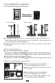
3. HFX-700M KIT Installation 3.1. Positioning the devices Main monitor Proper height: Door camera View Angle: 70cm (27.6") 170cm (66.9") 100cm (39.3") 165cm (64.9") 50cm(19.7") 50cm(19.7") The proper height of monitor or door camera is 160~170cm(63"~67") from the ground. This may vary on each installation. View range should be actively tested before complete. Viewing window of door camera is about 70cm up-n-down, and 100cm left-n-right.
3.2. Installation STAGE 1: Installation main monitor A. Fasten the wall mount bracket using the provided hardware. B. Fasten wires on terminals accordingly. (Refer to STAGE 3) C. Plug pin wires and mount the monitor unit on bracket. PT1 PT2 DG1 DG2 OUT+ OUTDR2 DR1 <+> POWER <-> Monitor Wall mount bracket Do not plug power at this stage. STAGE 2: Installation door camera A. Use screws wrench disassemble screw and remove door camera unit from bracket. B. Fasten wall mount bracket on position. C.
STAGE 3: Wiring and setting A. Wire the system from terminals to terminals as accordingly. B. Select and plug JP2 to its RIGHT( ) to disable automatic LED light supplement at night. Factory setting is LEFT( ) as enable. C. Select and plug JP1 to its RIGHT( ) for direct current output control. Factory setting has JP1 to its LEFT( ) for dry contact bridge control. (Refer to 3.
3.3. Door Release Options Each Door Camera on the system is able to operate and release one electric lock. On a full system with 2 door cameras, the user is able to release up to two electric locks. The system can only release one electric lock at a time, depending on which door camera the call originated from. There are two door release wiring options that work with the Video Intercom System.
4. HFX-700M KIT Test after installation Installed and with a good line, the need to test the system. 4.1. Basic function test A. Plug in the power supply. B. Press the call button on the door camera. C. Check and adjust doorbell volume. D. Check and adjust the picture quality. E. Listen to the door camera and adjust the speaker volume. F. Adjust view angle of the door camera. 4.2. Door release test(optional) A. For door strike installation instructions please refer to page 11. B.
5. HFX-700M KIT Operation Operating the video intercom system consists of responding to visitor calls from door camera, releasing a door strike from indoor monitor; audio and video monitoring from any indoor monitor; voice broadcast from one monitor to all others; engage intercom function after voice broadcast. 5.1. Visitor Calls from Door Camera A. When the Call button on the camera is pressed, All monitors on the system will ring with a chime sound and all monitors will be activated. B.
EXPANSION OPTIONS A. HFX-700M package consists a main monitor, a door camera, and a power adaptor for the monitor. B. With HFX-700M KIT as a basic, the system is capable of expanding up to a total of 4 indoor monitors and 2 door cameras. Expansion monitor can choose video(EX-700H) or non-video(EX-700A). System layout 1: NOTE: the system is capable of expanding up to a total of 4 monitors (1 main video monitor + 3 expansion video monitor) and 2 door cameras.
Wiring Diagram: A. Magnetic switch or external bell chime wiring, refer to page 10. B. Electric lock strike wiring, refer to page 11. C. Expansion video or non-video monitor wiring diagram is the same.
1. Expansion Video Monitor (EX-700H) 1.1. EX-700H Identification EX-700H 13 1 178mm (7.0 ) 15 12 2 5 6 36mm (1.42 ) 4 3 7 8 9 10 11 118mm (4.65 ) EX-700H identification: 1. 2. 3. 4. 5. 6. 7. 8. 9. 10. 11. 12. 13. 14. 15. 16. 14 3.
EX-700H Wall mount bracket Wiring terminals Wall mount bracket 1 PT1 PT1 PT2 PT2 136mm (5.35 ) OUT+ 2 OUTIN+ IN- 3 <+> POWER <-> 4 89mm (3.5 ) OUT+ OUTIN+ IN- <+> POWER <-> 8.4mm(0.
1.2. EX-700H Installation STAGE 1: Installation expansion monitor A. Fasten the wall mount bracket using the provided hardware. B. Fasten wires on terminals accordingly. (Refer to STAGE 2) C. Plug pin wires and mount the monitor unit on bracket. PT1 PT2 OUT+ OUTIN+ IN- <+> POWER <-> Monitor Wall mount bracket Do not plug power at this stage. STAGE 2: Wiring and setting A. Wire the system from terminals to terminals as accordingly.
1.3. EX-700H Operation Operates the same as the main monitor unit (Refer to page 13). 1.3.1.Broadcast and intercom function A. When system consists of main monitor and expansion monitor and an outdoor doorbell/camera unit, system can provide intercom function. B. Press intercom button from any monitor, all other monitors will react by making bell sound. At the same time, host can speak and broadcast voice message to all other monitors. C. The broadcast mode can last for 20 seconds.
2. Expansion Non-video Monitor (EX-700A) 2.1. EX-700A Identification 12 13 178mm (7.0 ) 14 11 1 4 5 36mm (1.42 ) 3 2 6 7 8 9 118mm (4.65 ) EX-700A identification: 1. 2. 3. 4. 5. 6. 7. 8. 9. 10. 11. 12. 13. 14. 15.
EX-700A Wall mount bracket Wiring terminals Wall mount bracket 1 PT1 PT1 PT2 PT2 136mm (5.35 ) OUT+ 2 OUTIN+ IN- 3 <+> POWER <-> 4 89mm (3.5 ) OUT+ OUTIN+ IN- <+> POWER <-> 8.4mm(0.
2.2. EX-700A Installation STAGE 1: Installation expansion monitor A. Fasten the wall mount bracket using the provided hardware. B. Fasten wires on terminals accordingly. (Refer to STAGE 2) C. Plug pin wires and mount the monitor unit on bracket. PT1 PT2 OUT+ OUTIN+ IN- <+> POWER <-> Monitor Wall mount bracket Do not plug power at this stage. STAGE 2: Wiring and setting A. Wire the system from terminals to terminals as accordingly.
2.3. EX-700HA Operation A. Operates the same as the main monitor unit (Refer to page 13). B. EX-700A only audio function, not video function. 2.3.1.Broadcast and intercom function A. When system consists of main monitor and expansion non-video monitor and an outdoor doorbell/camera unit, system can provide intercom function. B. Press intercom button from any monitor, all other monitors will react by making bell sound. At the same time, host can speak and broadcast voice message to all other monitors. C.
3. Door Camera (EX-700D) 3.1. EX-700D Identification 1 7 2 3 130mm (5.12") JP2 1 4 5 2 10 JP1 9 8 3 4 11 6 36mm (1.42") 98mm (3.86") EX-700D identification: 1. 2. 3. 4. 5. 6. 7. 8. 9. 10. 11.
3.2. EX-700D Installation STAGE 1: Installation door camera A. Use screws wrench disassemble screw and remove door camera unit from bracket. B. Fasten wall mount bracket on position. C. Fasten wires on terminals and select jumpers for desire function. (refer to STAGE 2) D. Mount door camera unit on bracket, secure the assembly screw. Screws wrench Pull out screw cover to access the screw Door camera Bracket STAGE 2: Wiring and setting A.
TECHNICAL SPECIFICATIONS HFX-700M(main monitor) 3.5" digital TFT-LCD 320 x 240 pixels 30 seconds time out; 90 seconds for conversation Auto Timer (intercom): 20 seconds time out; 90 seconds for conversation Operating Temperature: 14 F ~ 140 F, indoor Dimensions (w/ bracket): 4.65"(L) x 7.0"(W) x 1.42"(D) Power adaptor: input 100~240VAC 50/60Hz; output 23VDC/1A(24W), external Power consumption: standby 2.1W, operating 7.
EX-700H(optional expansion monitor) Display: Resolution: Auto Timer (visitor call): 3.5" digital TFT-LCD 320 x 240 pixels 30 seconds time out; 90 seconds for conversation Auto Timer (intercom): 20 seconds time out; 90 seconds for conversation Operating Temperature: 14 F ~ 140 F, indoor Dimensions (w/ bracket): 4.65"(L) x 7.0"(W) x 1.42"(D) Power adaptor: input 100~240VAC 50/60Hz; output 23VDC/1A(24W), external Power consumption: standby 1.4W, operating 3.
TROUBLE SHOOTING Before requesting service, check the troubleshooting quide to solve the problem. Problem Solution No power (no picture on monitor) Make sure AC plug is firmly inserted into the AC outlet. Make sure the power terminal is firmly connected into the monitor unit. Check to ensure polarity is correct. (Red=positive, Black=negative). System is on but no picture on the monitor Make sure the cable is cnnected securely between the master monitor and the camera.
SERVICE AND WARRANTY To receive after sales service, please provide the following information when contact. a. Name of the product b. Model and serial number of the product , c. The store s name where you purchased d. Date purchased e. Idea and area of possible problems Information Card Product name Model and serial number , The store s name Date purchased (receipt) The warranty statements a. This product is produced under strict internal quality control and inspection procedures. b.
http:// www.comelitusa.com Info@comelitusa.