
Specifications


GOLDCUP CONTROLS SERIES 200
TEST
thrust washer (6) over needle bearing.
5. Install O-ring (5) in the second groove from the end of the shaft., using installation
tool T-1
6. Install the servo shaft assembly in the control cover (10).
7. Install retaining ring (4) into the groove of the servo shaft extending through the
control cover.
8. Install spools (15) and/or (22) into the bores in the body. Note: reduced down diam-
eters must be to the outside, and spools must freely slip into the bores. Pump controls
use two short spools (22). Motor controls use one long spool, (15) on the side with the
spring, and one short spool (22), on the opposite side. See chart for spring location
relative to item (12) figure 2A.
9. Install spring (16) over the spool extension on indicated side.
10. Install plugs (17) with O-rings (16). Install remaining parts in plugs.
11. Place two spring washers (24), nested with the bent sections matching each other,
into the large hole in the servo link.
12. Place washer (11) against the spring washers.
13. Install O-ring into groove in the remaining shear seal (25). Note: This shear seal
does not contain the two .094” (2.4 mm) radius scallops in the face. Place on top of
washer (32). Position shear seal to match the lip on the servo link.
14. Install control on pump control pad, over dowels, with gasket, (26). Place new
Nyltite washers (3) on screws (2). Torque to 30 lbs-ft. (40.8 Nm).
1. Connect lever to input shaft. With unit running, manually stroke the shaft. Do not
exceed 100 lbs-in. (11.3 Nm) torque. Pump or motor cam shall follow the motion of the
input shaft.
Input shaft and cam shall return to the spring biased position when the lever is
released.
2. Set the maximum stop screw for full displacement. Set the minimum stop position.
For motor controls, minimum stroke shall be no less than 25% and no more than 33%
of full stroke, with the lever at minimum stroke and the minimum stop screw backed
away from contact with the piston. Caution! do not allow motor to exceed rated RPM.
For pump controls, set the minimum stop screw for zero displacement. Lock in posi-
tion.
3. Apply 300 to 600 psi servo supply to signal port. Control shaft shall rotate and
pump or motor shall follow stroke of input shaft.
“Y” port is adjacent to 1/8” plug (12)
4. Drop signal pressure to minimum. Control shall return to the spring offset position,
and pump or motor shall return to the initial displacement.
11
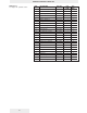
Pump Shaft Control Spring loc.
Rotation mounting to 1/8” plug (12)
clockwise A same
clockwise B opposite
c/clockwise A opposite
c/clockwise B same
Motor control mtg. Long spool and Spg.
loc. to 1/8” plug (12)
A same
B opposite
Note: The dowel pin in the arm must be positioned in the rectangular slot beside the
shaft hole. This will position the shear seal (8) face against the cover.
Pump shaft Control Signal Tank
rotation mounting port port
clockwise A Y X
clockwise B X Y
c/clockwise A X Y
c/clockwise B Y X
Motor control Signal port Tank port
mounting
A X Y
B Y X