
Specifications

GOLDCUP CONTROLS SERIES 600
REWORK OF WEAR PARTS
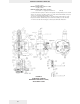
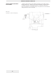
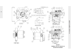
See Figure 6B-1
See Figure 6C
1. Install Lee Pluget (13) using installation tool and gage.
2. Install orifices (10) and (11) in body. Make sure that the orifice (10) in the deeper
bore extends past the wall of the valve bore and will not interfere with spools (25) or
(33) action.
3. Install 1/16 pipe plug (27) into cover (12). Plug must extend below bore, so it will
not interfere with spool (25).
4. Apply pipe sealant to the 1/8” pipe plugs (14) and install in the cover plate. Torque
to 100 in.-lbs. (11.3 Nm)
5. If stroker housing was removed from control cover, install O-ring (12-1A) in housing
and O-rings (12-3) and (12-5) on interface between parts. Slip servo shaft assembly
through the bore, and install screws (12-4). Torque to 25 lbs-ft. (33.9 Nm). Check for
free motion of shaft assembly. Remove shaft. Slip spools into their respective bores
and check for free travel. If tight, it may be necessary to carefully hone the bore, till
spools are free in bores. Position spool (25) in the bore with the slot, align the elongat-
ed hole centered over the slot and the grooved end toward the orifice (33).
6. Install O-ring (29) on nut (28) and the neutral bypass trimmer assembly into nut
(28). Install nut (28) into cover. Adjust trimmer assembly until the land on end of
assembly is centered in groove in spool (25), with elongated hole in spool centered on
slot in cover. Hold in place and install nut (31), O-ring (32), plug (6) and O-ring (44).
7. Install O-ring (29) on plug (30) and install on other end of this bore.
8. Install spools (33) and (36) into the other cross-bore in the cover (12). The slotted
end of spool (33) should be to the outside.
9. Install O-ring (29) on plug (35). Install spring (34) in plug and install plug in cover
as shown.
10. Install O-rings (40) on fitting (41). Install piston (42) in bore of body (39). Install
fitting (41) on body and install assembly in cover (12).
11. Install O-rings (44) and (45) on vent post (46). Install vent post in cover.
12. Install spring (47) and shoe (48) over vent post.
13. Install O-ring (19) on plug (18) and install in body (12).
14. Install O-ring (23-8) in groove of shear seal (23-5). Install shear seal with O-ring in
the large hole on the servo link, on the servo shaft side. Be certain that the shear seal
is sitting with the flange flush against the servo link surface.
15. Install needle bearing (23-9) over servo shaft and seat against the servo link.
Install thrust washer (23-4) over needle bearing.
16. Install spool (12) in stroker body. Press dowel (9) into clamp (8) to .500”
(12.7mm) dimension shown. Install screw (4) in clamp. Slip clamp into body to
engage groove in spool (12). Slip servo shaft assembly (23) through the body and
through the clamp, simultaneously engaging the pin on the servo arm with the slot in
the spool, (25) ref. 6B-1.
17. Tighten the clamp only enough to hold the clamp snugly against the bushing,
while permitting the shaft to turn in the clamp with light force.
18. Holding a flat plate against the ends of the spool bore, rotate the shaft clockwise
and counterclockwise, causing spool (12) to travel from flush one side to flush the
other side. Observe the position of the shear seal relative to the two 3/16 dowel holes
in the cover. Position such that the overlap is equal on each side. Eliminate end play
and torque screw (4) to 72 lbs-in, (8 Nm), locking the clamp to the shaft
19. Install spring guide (13) and spring (14) over screw (19). Install screw into screw
(18). Adjust to 2” compressed length on spring (14). Install 1/4-20 nut (17) and tight-
en.
20. Insert spring assembly in body (2). Adjust for .308” ((7.82 mm) extension of spring
guide beyond surface. Install O-ring (20) in body and locknut (15). Install locknut and l
acorn nut (16) on screw (18).
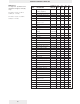
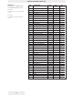
18. Install O-ring (20) in body and place assembly on stroker body, according to chart:
19. Using screws (24) bolt end connection (2) onto body (23).
62
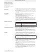
Description Rework
Servo plate face Fine stone to remove raised burrs & dings
Shear seal Fine stone to remove raised burrs & dings. Note:
grooves to supply balance pads must be present
and adequate.
Control cover Stone or lap inside face to remove raised burrs &
dings.
Spool Break sharp edges or dings.
Shoe Stone to remove raised burrs or dings.
Note: The shear seal will fit in one position only. Otherwise one side will be held up
by the lip of the servo link. Shear seal (23-5) must be installed to face against the
cover plate. This shear seal differs from shear seal (23-7) in that the face surface is
machined with two .094” (2.4 mm) radius scallops.