
Specifications
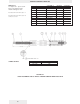

GOLDCUP CONTROLS SERIES 900
9A ELECTRIC STROKER
S23-12667 Feature 00 cross ctr. Pump
S23-12957 Feature 01 cross ctr. Pump
S23-12940 Feature 00 cross ctr.
P6R,P7R,P8R
S23-12734 Feature 00 CW-A,CCW-B-
Pump)
S23-12733 Feature 00 CCW-A,CW-B-
Pump)
S23-15050 Feature 0* A Mtg. Motor)
S23-15051 Feature 0* B Mtg. Motor)
DESCRIPTION
DISASSEMBLY
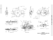
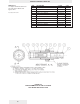
See Figure 9A
REWORK OF WEAR PARTS
ASSEMBLY
The 9A consists of one or two electric proportional pressure control valves mounted on
the 8A cover to provide the pilot pressure signal. It is a simple electrohydraulic control
with comparable performance to the 5A in most applications. Refer to 8A for stroker
description.
The Jupiter 900 Driver Card has been developed to accompany the 9A control with
24V coil.
1. Disconnect connector (46) from coil (52).
2. Remove proportional valve or valves from block (39). Do not attempt disassembly
of the valve, other than replacement of the coil, (52) and external O-rings, (38-a), (38-
b) and (38-c).
3. Remove screws (2) from control. Remove proportional valve block (39) from con-
trol. Remove control from pump.
4. Examine orifices (37) for plugging or contamination. Examine servo plate for exces-
sive scratching on surface. Note if orifices in stem are open. If servo plate is
scratched or orifices appear to be plugged, remove plate and servo stem by removing
two soc. setscrews from plate, then alternately loosening the two button hd. screws
under the setscrews.
5. Remove retaining ring (4) and press the shaft assembly through the valve body
(10).
6. Examine shoes (8) and (18) for contamination in balance pads and excessive
scratching on shoe faces. Note the two shoes are not identical and must be installed
in the proper position upon reassembly.
7. Remove the plug (13) with the stop assembly intact.
8. Remove the centering adjustment screw (23) with the spool assembly and stop
assembly intact. Note: positive centering and control starting current are determined
by the spring preload. Do not disassemble or change unless setting is incorrect.
9. Clean and examine all parts for breakage or evidence of abnormal wear.
All parts are to be inspected and be free of material defects, dirt, scratches, or any for-
eign material.
All parts are to be cleaned with a suitable cleaning solvent and all cores and passages
blown out with clean dry compressed air.
After cleaning and inspection, all parts are to be covered with a light film of oil and
should be protected from dirt and excessive handling until assembled onto the unit.
During assembly, lapped and ground surfaces should be kept lubricated and protected
from nicks or surface damage.
1. Apply pipe sealant to the 1/8” pipe plug (12) and install in the cover plate. Torque to
100 lbs-in. (11.3 Nm).
87
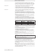
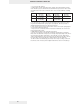
Description Rework
Servo plate face Fine stone to remove raised burrs & dings
Shear seal Fine stone to remove raised burrs & dings. Note:
grooves to supply balance pads must be present
and adequate.
Control cover Stone or lap inside face to remove raised burrs &
dings.
Spool Break sharp edges or dings.