
Service manual

XL-520W/CP-520
– 10 –
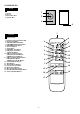
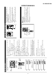
Figure 10-2
Figure 10-3
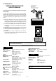
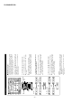
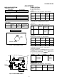
1. This CD unit need adjustment as follow.
CD SECTION
Figure 10-4
CD Test Mode
Adjustment Part
Value/Adjusting Method
Instrument Connection
Step 1 VR803 (Focus Offset) DC + 40 mV (FEI>VRO) FEI (R826) and VRO
(1-Pin of TP801)
Step 4 VR802 (Tracking Error Balance) *1 (See Fig. 9-2) TSO (3-Pin of TP801)
and VRO (1 Pin of TP801)
*1: Adjust to obtaiin vertically symmetrical waveform (Fig. 10-2) with respect toreference DC level. The reference level is VRO
(Approx DC 2.1V).
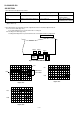
2. This CD unit have the following automatic adjustment function. Automatic adjustment item.
2-1: Focus Servo Gain (Fig. 10-3)
Focus Gain Adjustment is performed when disc is changed.
2-2: Tracking Servo Gain (Fig. 10-4)
Tracking Gain Adjustment is performed when disc is changed and disc is playbacked.
TSO
VRO
1
SYMMETRICAL
UP AND DOWN
FEI
FSO
1
2
TSO
TS2O
1
2
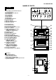
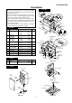
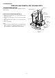
Figure 10-1 ADJUSTMENT POINTS
VR802 VR803
TP801
TRACKING
ERROR
BALANCE
FOCUS
OFFSET
T
S
O
N
C
V
R
O
CD SERVO PWB