OPERATOR’S AND PARTS MANUAL HP400/HP450/HP600/HP750/HP1000 COLD PLANERS FOR SKID-STEER LOADERS SERIAL NUMBER: ___________________ MODEL NUMBER: ___________________ 800-922-2981 I www.paladinbrands.com Manual Number: OM666 Part Number: 75566 Rev. 3 P.O.
TABLE OF CONTENTS TO THE OWNER ............................................................................................. A SAFETY PRECAUTIONS ................................................................................ B To The Operator Before You Start Working With The Attachment Transporting The Attachment Maintenance INTERNATIONAL SYMBOLS ......................................................................... C PREOPERATION ......................................................................
A A TO THE OWNER GENERAL COMMENTS Congratulations on the purchase of your new BRADCO product! This product was carefully designed and manufactured to give you years of dependable service. Only minor maintenance (such as cleaning and lubricating) is required to keep it in top working condition. Be sure to observe all safety precautions and maintenance procedures, as described in this manual. ABOUT THIS MANUAL This manual has been designed to help you do a better, safer job.
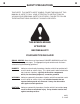
B B SAFETY PRECAUTIONS TAKE NOTE! THIS SAFETY ALERT SYMBOL FOUND THROUGHOUT THIS MANUAL IS USED TO CALL YOUR ATTENTION TO INSTRUCTIONS INVOLVING YOUR PERSONAL SAFETY OR OTHERS. FAILURE TO FOLLOW THESE INSTRUCTIONS CAN RESULT IN INJURY OR DEATH. THIS SYMBOL MEANS: ATTENTION! BECOME ALERT! YOUR SAFETY IS INVOLVED! SIGNAL WORDS: Note the use of signal words DANGER, WARNING, and CAUTION with the safety messages.
B B SAFETY PRECAUTIONS GENERAL INFORMATION This section is composed of various warnings and safety tips. Read and learn all the information in this section before you attempt to use your attachment. Also read your vehicle owner's manual before using your equipment. This knowledge will help you operate your unit safely. Do not take this information lightly, it is presented for your benefit and for the benefit of others working around you.
B B SAFETY PRECAUTIONS 9. Never try to board equipment while it is moving. 10. Turn off engine before performing maintenance. All maintenance can be performed with the machine lowered. If lift arms must be left raised for any reason, use a positive lift arm lock to secure the arms in place. Serious damage or personal injury could result from lift arms accidentally lowering. 11. Reduce speed when driving over rough terrain, on a slope, or turning to avoid overturning the loader. 12.
B B SAFETY PRECAUTIONS 3. Observe proper maintenance schedules and repairs to keep the unit in safe working order. 4 Always wear safety goggles or glasses when working on equipment. 5. Use a drift and hammer when pressing out pins to prevent the pin from shattering. 6. Use only manufacturer recommended replacement parts. Other parts may be substandard in fit and quality. WARNING! Escaping fluid under pressure can have sufficient force to penetrate the skin causing serious personal injury.
C C INTERNATIONAL SYMBOLS As a guide to the operation of your equipment, various international symbols have been utilized on the instruments and controls. The symbols are shown below with an indication of their meaning.
D D PRE-OPERATION HIGH FLOW COLD PLANERS GENERAL INFORMATION The purpose of this manual is to assist in setting up, operating and maintaining your BRADCO planer. Read it carefully. It furnishes information and instructions that will help you achieve years of dependable performance. Unless otherwise noted right and left are determined from the position of the skid-steer operator sitting in the operator's seat facing forward.
D D PRE-OPERATION HIGH FLOW COLD PLANERS MAJOR NOMENCLATURE Throughout this manual, reference is made to various attachment components. The purpose of this section is to acquaint you with the various names of these components. This knowledge will be helpful when reading through the manual or when ordering service parts.
E E PLANER ASSEMBLY 16", 18", 24", 30" & 40" COLD PLANER ASSEMBLIES DIAGRAM 1 OF 3 6 5 4 3 2 8 1 7 9 21 10 23 11 12 22 13 18 31 24 25 20 19 17 16 26 27 15 14 28 40" PLANER ONLY 32 DRUM IDLER ASSEMBLY 36 34 33 29 18 37 38 30 35 9350 11-3-05-5
E E PLANER ASSEMBLY 16", 18", 24", 30" & 40" COLD PLANER ASSEMBLIES LIST 1 OF 3 NO REQ'D PART NO. 1 4 4 4 2 4 2 2 1022 1502 1513 17737 1589 17729 18685 .31" UNC X 1.00" Hex Capscrew .31" Lock Washer .31" Flat Washer Depth Indicator Set Screw Pivot Plate Bushing 1 1 1 2 1 1 1 1 1 2 1 1 1 17677 1652 64727 17734 17725 18651 17600 19431 101085 6616 17676 1652 64727 Right Link 1.25" Snap Ring 1.
E E PLANER ASSEMBLY 16", 18", 24", 30" & 40" COLD PLANER ASSEMBLIES DIAGRAM 2 OF 3 6 5 4 3 2 8 1 7 9 21 10 23 11 12 22 13 18 31 24 25 20 19 17 16 26 27 15 14 28 40" PLANER ONLY 32 DRUM IDLER ASSEMBLY 36 34 33 29 18 37 38 30 35 9354 11-3-05-5
E E PLANER ASSEMBLY 16", 18", 24", 30" & 40" COLD PLANER ASSEMBLIES LIST 2 OF 3 NO REQ'D PART NO. 20 5 5 5 5 1044 1503 1514 1226 .38" UNC X 1.25" Hex Capscrew .38" Lock Washer .38" Flat Washer .38" UNC Hex Nut 21 22 2 1 1 1 1 1 2 2 2 2 2 2 1102 18656 17663 19545 101130 19560 1043 1503 1514 1226 17666 1841 .50" UNC X 5.00" Hex Capscrew Door (16" & 18" Planer) Door (24" Planer) Door (30" Planer) Door (40" Planer) Latch .38" UNC X 1.00" Hex Capscrew .38" Lock Washer .38" Flat Washer .
E E PLANER ASSEMBLY 16", 18", 24", 30" & 40" COLD PLANER ASSEMBLIES DIAGRAM 3 OF 3 1 5 3 2 4 16 2 6 17 7 8 9 13 10 16 15 14 11 9 12 9352 11-3-05-3
E E PLANER ASSEMBLY 16", 18", 24", 30" & 40" COLD PLANER ASSEMBLIES LIST 3 OF 3 NO REQ'D PART NO.
E E DRUM AND PICK OPTIONS 1 3 2 .54" 1.04" 1.89" 1.77" .14" 3.56" 3.51" 1.50" 1.50" 1.
E E DRUM AND PICK OPTIONS DRUM OPTIONS (INCLUDES STANDARD ALL-PURPOSE PICKS) #1 DESCRIPTION 16" Standard Drum (16" Cold Planer) 18" Standard Drum (18" Cold Planer) 24" Standard Drum (24" Cold Planer) 30" Standard Drum (30" Cold Planer) 40" Standard Drum (40" Cold Planer) 2.50" Slot Cutter Drum (All Planers) 4.00" Slot Cutter Drum (All Planers) 6.
E E WHEEL ASSEMBLY ASSEMBLY #18702 1 2 3 4 5 6 7 8 9 10 11 9358 3-2-04
E E WHEEL ASSEMBLY ASSEMBLY #18702 NO REQ'D PART NO. DESCRIPTION 1 2 3 4 5 1 3 3 3 1 17667 1646 1505 1811 1514 Wheel Mounting Bracket .50" Hard Flat Washer .50" Lock Washer .50" UNC X 1.50" Hex Capscrew - Grade 8 .38" Flat Washer 6 7 8 9 10 1 1 1 1 1 1503 1042 17673 6616 17671 .38" Lock Washer .38 "UNC X .
E E HYDRAULIC ASSEMBLY ASSEMBLY #19220 1 2 3 4 10 2 1 7 6 5 4 1 9 2 6 8 5 11 5 15 5 13 12 16 14 5 1 8 24 8 18 5 1 16 21 17 19 23 22 15 20 5 1 2 HYDRAULIC MOTOR 9356 9-22-04
E E HYDRAULIC ASSEMBLY ASSEMBLY #19220 NO REQ'D PART NO. 1 2 3 4 5 12 8 2 2 12 6612 61079 73461 89520 3434 Snap Ring 1.00" Thrust Washer 1.00" x .06" Cylinder Pin Cylinder Assembly (Depth Control) 90° Elbow 6MBo-6MJ 6 7 8 2 1 6 6 6 1 2 2 1 30313 19195 1022 1502 1513 19215 1836 1634 100434 45° Elbow 6MBo-6MJ Valve Cover .31" UNC X 1.00" Hex Capscrew .31" Lock Washer .31" Flat Washer Wire Harness - Four Function Control 10-24 UNC Hex Nut 10-24 X .
HP400 & HP450 PLANER HOSE KIT 16" & 18" PLANER HOSE SET #38168 TO SKID-STEER 1 2 3 DEPTH CYLINDER SIDE SHIFT CYLINDER 7 4 8 6 5 5 DEPTH CYLINDER 17 16 12 6 CONTROL VALVE 9 11 CYLINDER CONTROL VALVE 10 14 13 15 TILT CYLINDER HYDRAULIC MOTOR 9366 9-22-04
HP400 & HP450 PLANER HOSE KIT 16" & 18" PLANER HOSE SET #38168 NO REQ'D PART NO. DESCRIPTION 1 2 3 4 5 1 1 1 1 2 19638 22520 38159 38159 37016 Male Coupler Female Coupler Hose .75" X 75" 12FJX-12MBo-HS Hose .75" X 75" 12FJX-12MBo-HS Hose .25" X 15" 6FJX-6FJX 6 7 8 9 10 2 1 1 1 1 38175 37599 38108 37236 38106 Hose Hose Hose Hose Hose .25" X 17" .25" X 66" .25" X 54" .25" X 22" .
HP600 PLANER HOSE KIT 24" PLANER HOSE SET #38169 TO SKID-STEER 1 2 3 DEPTH CYLINDER SIDE SHIFT CYLINDER 7 4 8 6 5 5 DEPTH CYLINDER 17 16 12 18 CONTROL VALVE 9 11 CYLINDER CONTROL VALVE 10 14 13 15 TILT CYLINDER HYDRAULIC MOTOR 9368 9-22-04
HP600 PLANER HOSE KIT 24" PLANER HOSE SET #38169 NO REQ'D PART NO. DESCRIPTION 1 2 3 4 5 1 1 1 1 2 19638 22520 38159 38159 37016 Male Coupler Female Coupler Hose .75" X 75" 12FJX-12MBo-HS Hose .75" X 75" 12FJX-12MBo-HS Hose .25" X 15" 6FJX-6FJX 6 7 8 9 10 1 1 1 1 1 37236 37599 38108 37421 37804 Hose Hose Hose Hose Hose .25" X 22" .25" X 66" .25" X 54" .25" X 25" .
HP750 PLANER HOSE KIT 30" PLANER HOSE SET #38170 TO SKID-STEER 1 2 3 DEPTH CYLINDER SIDE SHIFT CYLINDER 7 4 8 6 5 18 17 DEPTH CYLINDER 16 12 19 CONTROL VALVE 9 11 CYLINDER CONTROL VALVE 10 14 13 15 TILT CYLINDER HYDRAULIC MOTOR 9370 9-22-04
HP750 PLANER HOSE KIT 30" PLANER HOSE SET #38170 NO REQ'D PART NO. DESCRIPTION 1 2 3 4 5 1 1 1 1 1 19638 22520 38159 38159 37282 Male Coupler Female Coupler Hose .75" X 75" 12FJX-12MBo-HS Hose .75" X 75" 12FJX-12MBo-HS Hose .25" X 24" 6FJX-6FJX 6 7 8 9 10 1 1 1 1 1 38154 37599 38108 35694 37805 Hose Hose Hose Hose Hose .25" X 17" .25" X 66" .25" X 54" .25" X 34" .
HP1000 PLANER HOSE KIT 40" PLANER HOSE SET #38308 TO SKID-STEER 1 2 3 DEPTH CYLINDER SIDE SHIFT CYLINDER 7 4 8 6 5 18 17 DEPTH CYLINDER 16 12 19 CONTROL VALVE 9 11 CYLINDER CONTROL VALVE 10 14 13 15 TILT CYLINDER HYDRAULIC MOTOR 10428 11-3-05
HP1000 PLANER HOSE KIT 40" PLANER HOSE SET #38308 NO REQ'D PART NO. DESCRIPTION 1 2 3 4 5 1 1 1 1 1 19638 22520 38159 38159 35694 Male Coupler Female Coupler Hose .75" X 75" 12FJX-12MBo-HS Hose .75" X 75" 12FJX-12MBo-HS Hose .25" X 34" 6FJX-6FJX 6 7 8 9 10 1 1 1 1 1 38219 37599 38108 35694 37805 Hose Hose Hose Hose Hose .25" X 27" .25" X 66" .25" X 54" .25" X 34" .
E E WATER KIT ASSEMBLY #19216 1 2 3 4 5 6 7 6 8 6 7 6 10 11 12 8 6 7 6 10 11 9 12 10 11 12 9388 3-3-04
E E WATER KIT ASSEMBLY #19216 NO REQ'D PART NO.
E E WATER KIT ASSEMBLY #103031 1 2 3 4 5 6 7 6 8 6 7 6 10 11 8 6 12 10 6 11 8 6 12 7 10 6 11 9 12 10 11 12 10430 11-3-05
E E WATER KIT ASSEMBLY #103031 NO REQ'D PART NO.
E E CYLINDER ASSEMBLY ASSEMBLY #101540 1 2 7 8 9 3 4 10 11 5 12 13 6 9829 9-22-04
E E CYLINDER ASSEMBLY ASSEMBLY #101540 NO REQ'D PART NO. DESCRIPTION 1 2 3 4 5 1 1 1 1 1 1482 6992 52644 101539 89527 Hex Nut Piston Washer Cylinder Tube Cylinder Gland 6 7 8 9 10 1 1 1 1 1 101537 4637* 4636* 4635* 4633* Cylinder Rod O-Ring Piston Ring O-Ring O-Ring 11 12 13 1 1 1 4634* 45262* 4981* Back-Up Washer Poly-Pak Seal Rod Wiper NOTE: Seal kit #45581 includes all parts marked with an asterisk (*). Parts are not sold separately.
E E CYLINDER ASSEMBLY ASSEMBLY #89520 1 2 7 8 9 3 4 10 11 5 12 13 6 9362 3-3-04
E E CYLINDER ASSEMBLY ASSEMBLY #89520 NO REQ'D PART NO. DESCRIPTION 1 2 3 4 5 1 1 1 1 1 1482 6992 52644 89521 89527 Hex Nut Piston Washer Cylinder Tube Cylinder Gland 6 7 8 9 10 1 1 1 1 1 89522 4637* 4636* 4635* 4633* Cylinder Rod O-Ring Piston Ring O-Ring O-Ring 11 12 13 1 1 1 4634* 45262* 4981* Back-Up Washer Poly-Pak Seal Rod Wiper NOTE: Seal kit #45581 includes all parts marked with an asterisk (*). Parts are not sold separately.
E E CYLINDER ASSEMBLY ASSEMBLY #89535 1 2 7 8 9 3 4 10 5 11 12 13 14 6 9364 3-3-04
E E CYLINDER ASSEMBLY ASSEMBLY #89535 NO REQ'D PART NO. DESCRIPTION 1 2 3 4 5 1 1 1 1 1 1483 50252 5421 89536 77458 Hex Nut Piston Washer Cylinder Tube Cylinder Gland 6 7 8 9 10 1 1 1 1 1 89537 4645* 4644* 4641* 4509* Cylinder Rod O-Ring Piston Ring O-Ring O-Ring 11 12 13 14 1 1 1 1 4510* 45219* 45250* 45389* Back-Up Washer Poly-Pak Seal O-Ring Rod Wiper NOTE: Seal kit #45617 includes all parts marked with an asterisk (*). Parts are not sold separately.
F F INSTALLATION INSTRUCTIONS GENERAL INFORMATION The following instructions will help you to mount your planer onto your skid-steer loader. The planer uses the quick-attach system for ease of installation. Therefore, if you know how to attach your loader bucket, attaching the cold planer should prove no problem. Remember to read all safety warnings, decals and operating instructions before operating the attachment. If there is any portion of this manual that you do not understand, contact your dealer.
F F INSTALLATION INSTRUCTIONS 8. Following all standard safety practices, start the skid-steer and run all cylinders through their full cycle to purge any air from the system. Check that all controls function in accordance with the operating control decal. 9. If your planer is equipped with an optional water kit, install the female coupler supplied to your water line coming from the water tank on the skid-steer. Connect the female coupler to the male coupler on the planer water kit.
G G OPERATING INSTRUCTIONS GENERAL INFORMATION The BRADCO planer attaches to the toolbar/quick-attach mechanism of your skid-steer loader. Due to this arrangement, thorough knowledge of the skid-steer controls is necessary for machine operation. Read and understand your skid-steer operator's manual for information regarding skid-steer operation before attempting to use the planer. Check the surface to be planed. The standard all purpose picks can be used to mill both asphalt and concrete.
G G OPERATING INSTRUCTIONS NOTE: Hydraulic cylinders tilt the planer, adjust the depth of both the left and right side of the planer individually, and also shift the planer to the left or right. 3. Increase engine RPM and with the drum turning you can make any necessary adjustments to the side shift. Do not side shift the cold planer during milling operation. Once the desired side shift position has been achieved you are ready to begin. The drum will not cut in a side to side motion.
G G OPERATING INSTRUCTIONS CAUTION! Periodic observation must be made of the transmission oil temperature indicator when planing with high flow hydraulic systems. Depending on the ambient temperature and the duty cycle of the machine, hydraulic oil may overheat. If indicator comes on, shut off the cold planer and allow the skid-steer to idle until the temperature falls below 160° Fahrenheit. If the system continues running hot it may be necessary to clean any debris from the oil cooler and radiator.
G G OPERATING INSTRUCTIONS DEEP CUTS To achieve a deep cut the width of the drum, make the first cut at the recommended depth for the material being milled and then reposition the planer at the beginning of the pass and reset for double the recommended depth. Example: Make the first cut with the depth controls set at 2" and then set the depth control at 4" for the second pass and so on and so forth until the desired depth is obtained.
H H LUBRICATION GENERAL INFORMATION Economical and efficient operation of any machine is dependent upon regular and proper lubrication of all moving parts with a quality lubricant. Neglect leads to reduced efficiency, wear, breakdown and needless replacement of parts. All parts provided with grease fittings should be lubricated as indicated. If any grease fittings are missing, replace them immediately. Clean all fittings thoroughly before using the grease gun. IMPORTANT: Avoid excessive greasing.
L L MAINTENANCE & SERVICE GENERAL INFORMATION Regular maintenance is the key to long equipment life and safe operation. Maintenance requirements have been reduced to an absolute minimum. However it is very important that these maintenance functions be performed as described below. WARNING! Never do any maintenance to the planer while it is running. Exercise the MANDATORY SAFETY SHUTDOWN PROCEDURE BEFORE working on or around the planer. • DAILY Check to be sure case drain coupler is completely engaged.
L L MAINTENANCE & SERVICE IMPORTANT: When replacing parts use only factory approved replacement parts. Manufacturer will not claim responsibility for use of unapproved parts or accessories and/or other damages as a result of their use. PICK REPLACEMENT Picks should be replaced if you are changing to a different application pick, they are broken, worn, flat spot or are seized in the pick holder and do not rotate freely. WARNING! Always wear safety glasses with side shields when striking metal.
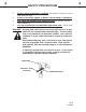
L L MAINTENANCE & SERVICE CHANGING THE DRUM Due to the weight of the unit, place the planer in a convenient location with a hoist available for lifting the planer off the drum. 1. Remove the right side plate by first removing the two bolts in the retainer and then loosen the ten .50" bolts on the clamp plates. Slide the right side plate off. LOOSEN BOLTS ON CLAMP PLATE REMOVE RETAINER LOOSEN BOLTS ON CLAMP PLATE RIGHT SIDE PLATE INSIDE OF DRUM 2. 3. 4. 5.
L L MAINTENANCE & SERVICE 3. Check to be sure the new planetary is filled with oil. If not, fill with approximately 2 quarts of Castrol SP 320 gear oil. 4. Remove the hydraulic motor from the planetary. Scrape any silicone from the hydraulic motor and apply new RV 10 silicone to the motor to seal the connection between the motor and the planetary. Bolt the hydraulic motor onto the new planetary using the existing hardware. 5. Position the new planetary into the PLANER BY UNBOLTING .62" X 2.
N N TROUBLESHOOTING PROBLEM Motor on the planer will not operate. POSSIBLE CAUSE POSSIBLE REMEDY Auxiliary hoses not hooked up to the skid-steer. Engage Couplers Obstruction in hydraulic lines. Remove obstruction and replace if necessary. Hydraulic motor damaged or seals blown. Call Bradco service department for instructions. Skid-steer auxiliary valve not engaged. Engage auxiliary valve. Insufficient hydraulic flow from the skid-steer. Refer to skid-steer's owners manual.
N N TROUBLESHOOTING PROBLEM Excessive oil temperature. A Hydraulic cylinder not operating. POSSIBLE CAUSE Hydraulic oil level too low. Refer to skid-steer's owners manual Obstruction in hydraulic lines. Remove obstruction and replace if necessary. Hydraulic oil or oil filter in skid-steer is dirty. Refer to skid-steer's owners manual. Relief valve setting adjusted too low. Refer to skid-steer's owners manual. Couplers not engaged. Engage couplers.
O O BOLT TORQUE BOLT TORQUE SPECIFICATIONS GENERAL TORQUE SPECIFICATION TABLE Use the following torques when special torques are not given. These values apply to fasteners as received from suppliers, dry, or when lubricated with normal engine oil. They do not apply if special graphited or moly disulphide greases or other extreme pressure lubricants are used. This applies to both UNF and UNC threads. Remember to always use grade five or better when replacing bolts. SAE Grade No.
P P SPECIFICATIONS COLD PLANER B C A E D SPECIFICATION DESCRIPTION 16" 18" 24" 30" 40" A. Overall Width ............................ 64.94" ...... 64.94" ....... 64.94" ...... 64.94" ..... 64.94" B. Overall Height ........................... 34.57" ...... 34.57" ....... 34.57" ...... 34.57" ..... 34.57" C. Overall Length .......................... 50.30" ...... 50.30" ....... 50.30" ...... 50.30" ..... 50.30" D. Planing Width ........................... 16.00" ...... 18.00" ....... 24.00" ...... 30.
Q Q DECALS DECAL PLACEMENT GENERAL INFORMATION The diagram on this page shows the location of the decals used on the BRADCO Cold Planers. The decals are identified by their part numbers, with reductions of the actual decals located on the following pages. Use this information to order replacements for lost or damaged decals. Be sure to read all decals before operating the attachment. They contain information you need to know for both safety and product longevity.
Q Q DECALS STAND CLEAR STAND CLEAR PART #40161 DANGER! PINCH POINTS PART #40149 WARNING! HIGH PRESSURE FLUID PART #40151 WARNING WARNING! READ MANUAL PART #40150 DANGER! FLYING DEBRIS PART #40719 WARNING! PART #4468 9406 7-27-04-2
Q Q DECALS BRADCO LOGO PART #40113 ANGLE INDICATOR PART #40723 12345678901234567890123456789012123456789012345678901234567890121234567890123456789 12345678901234567890123456789012123456789012345678901234567890121234567890123456789 12345678901234567890123456789012123456789012345678901234567890121234567890123456789 12345678901234567890123456789012123456789012345678901234567890121234567890123456789 12345678901234567890123456789012123456789012345678901234567890121234567890123456789 12345678901234567890123456
R R PREDELIVERY CHECKLIST GENERAL INFORMATION The following is a list of areas that should be inspected by the dealer prior to delivery of the attachment to the customer. The customer should check the list and make sure that the dealer has completed the inspection. Completion of this checklist will help insure that the customer receives the attachment in complete working order, ready to install. PREDELIVERY CHECKLIST - CHECK AND ADJUST AS NECESSARY 1.
S S LIMITED WARRANTY All new Bradco products are warranted to be free from defects in materials or workmanship which may cause failure under normal usage and service when used for the purpose intended.