XV-DW100U SERVICE MANUAL SY9U3XVDW100U LCD PROJECTOR XV-DW100U MODEL In the interests of user-safety (Required by safety regulations in some countries) the set should be restored to its original condition and only parts identical to those specified should be used. CONTENTS Page • • • • • • • • • • • • SPECIFICATIONS.............................................. 2 IMPORTANT SERVICE SAFETY NOTES .......... 3 NOTE TO SERVICE PERSONNEL .................... 4 OPERATION MANUAL .............................
XV-DW100U Specifications 2
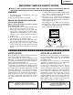
XV-DW100U IMPORTANT SERVICE SAFETY NOTES Ë Service work should be performed only by qualified service technicians who are thoroughly familiar with all safety checks and servicing guidelines as follows: » Use an AC voltmeter with sensitivity of 5000 ohm per volt., or higher, sensitivity to measure the AC voltage drop across the resistor (See Diagram). » All checks must be repeated with the AC plug connection reversed.
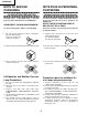
XV-DW100U NOTE TO SERVICE PERSONNEL 12345678901234567890123456789012123456789012345 12345678901234567890123456789012123456789012345 NOTE POUR LE PERSONNEL D’ENTRETIEN 12345678901234567890123456789012123456789012345 UV-RADIATION PRECAUTION 12345678901234567890123456789012123456789012345 12345678901234567890123456789012123456789012345 PRECAUTION POUR LES RADIATIONS UV 12345678901234567890123456789012123456789012345 12345678901234567890123456789012123456789012345 The light source, metal halide lamp, in th
XV-DW100U 12345678901234567890123456789012123456789012345 12345678901234567890123456789012123456789012345 12345678901234567890123456789012123456789012345 12345678901234567890123456789012123456789012345 12345678901234567890123456789012123456789012345 12345678901234567890123456789012123456789012345 UV-RADIATION PRECAUTION (Continued) 1234567890123456789012345678901212345678901234 1234567890123456789012345678901212345678901234 1234567890123456789012345678901212345678901234 PRECAUTION POUR LES RADIATIONS UV
XV-DW100U WARNING: High brightness light source, do not stare into the beam of light, or view directly. Be especially careful that children do not stare directly in to the beam of light. WARNING: TO REDUCE THE RISK OF FIRE OR ELECTRIC SHOCK, DO NOT EXPOSE THIS UNIT TO MOISTURE OR WET LOCATIONS. CAUTION The lighting flash with arrowhead within a triangle is intended to tell the user that parts inside the product are risk of electric shock to persons. RISK OF ELECTRIC SHOCK.
XV-DW100U Location of Controls Numbers next to the part names refer to the main pages in this manual where the topic is explained.
XV-DW100U Operating the Wireless Mouse Remote Control Remote Control Front View Top View Remote control signal transmitter MUTE button POWER buttons (ON/OFF) VOLUME buttons ( / ) LENS button MENU button Rear View ADJUSTMENT buttons ( / / ENTER button INPUT 1 button FREEZE button INPUT 2 button PICTURE MODE button VIDEO button / ) UNDO button GAMMA button RGB/COMPONENT button AUTO SYNC button MAIN POWER switch emote control BACKLIGHT button Bottom View Wired remote control input Inser
XV-DW100U Remote Control Positioning • The remote control can be used to control the projector within the ranges shown below. • The signal from the remote control can be reflected off the screen for easy operation. However, the effective distance of the signal may differ due to the screen material.
XV-DW100U Connection Pin Assignments Analog Computer 1 and 2 Signal Input Ports: 15-pin mini D-sub female connector 1 6 11 5 10 15 Computer Input Analog 1. Video input (red) 2. Video input (green/sync on green) 3. Video input (blue) 4. Reserve input 1 5. Composite sync 6. Earth (red) 7. Earth (green/sync on green) 8. Earth (blue) 9. 10. 11. 12. 13. 14. 15.
XV-DW100U Dimensions 2 5/64 (53) 49/64 (19.5) Rear View 2 3/8 (60.5) 2 3/16 (55.
XV-DW100U REMOVING OF MAJOR PARTS 1. Removing the Intake cover, lamp unit and lens cover. 1-1. 1-2. 1-3. 1-4. 1-5. Detach the Intake cover. Remove the four lock screws off the inner filter frame. Detach the frame. Remove the lock screw off the lamp cover. Slide and detach the lamp cover. Remove the three lock screws off the lamp unit and detach the lamp unit. Remove the lens cover lock screw, and turn and detach the lens cover. 2. Removing the rear cabinet. 2-1.
XV-DW100U 3. Removing the top cabinet. 3-1. Remove the four lock screws off the top cabinet. 3-2. Unhook the top cabinet by pressing the center of both sides of the bottom cabinet as well as the hook on the front (all marked with `). Slowly lift the back of the cabinet and disconnect the operation key unit connector (KY) and the speaker connector (SP). Then detach the top cabinet.
XV-DW100U 4. Removing the PWB units 4-1. Remove the five lock screws off the PC I/F unit. Lift and detach the unit off the output unit. 4-2. Disconnect the connectors from the output unit. 4-3. Remove the four lock screws off the output units. Remove also the lock screw off the ground fixture and detach the ground fixture. Lift and detach the output, terminal and signal units.
XV-DW100U 5. Removing the optical mechanism unit 5-1. Remove the two lock screws off the lamp socket holder. Detach the holder. 5-2. Disconnect the ground wire from the power unit. 5-3. Remove the six lock screws off the optical mechanism unit. Lift and detach the unit.
XV-DW100U 6. Removing the ballast / filter / sound-out unit assembly. 6-1. Disconnect the connector (BA) from the AC power switch. 6-2. Disconnect the ground wire from the inlet unit. 6-3. Remove the two lock screws off the ballast/filter/sound-out unit assembly. Detach the assembly. 7. Removing the power unit 7-1. Remove the three lock screws off the power PWB. Detach the power unit. 8. Removing the AC power switch and inlet unit. 8-1.
XV-DW100U RESETTING THE TOTAL LAMP TIMER When the lamp has been replaced, reset the total lamp timer in the following steps. Resetting procedure 1. While holding down the “ENTER”, “ADJ."” and “ADJ.|” keys on the set at the same time, turn on the POWER ON key. 2. Now the total lamp timer is reset to zero. “000H” appears on the screen. ENTER ADJ." ADJ.| Lamp The lamp in this projector operates for approximately 2,000 cumulative hours, depending on the usage environment.
XV-DW100U THE OPTICAL UNIT OUTLINE Layout of the optical system Note: Layout for positioning the optical system.
XV-DW100U CONVERGENCE AND FOCUS ADJUSTMENT » Start the convergence and focus adjustments with the top cabinet and the LCD cover removed but the power on. Use the remote control to adjust the image. Take the following procedures. 1. Focusing the projection lens (A) Replacing all the 3 LCD panels 1. Before replacing all the 3 LCD panels, project an image on the screen and bring it into focus. 2. Replace the panels with new ones.
XV-DW100U Notes : 1 The eccentric cam is used for convergence adjustment. This means that the cam’s turning and the linear movement are not always uniform. 2 This model is not equipped with the LCD image adjustment mechanism. This is because the dichroic prism is used for image formation. When the LCD panels all get into the best focus, the images are almost completely converged.
XV-DW100U Convergence and Focus Adjustments at a Glance Adjustment directions Adjustment Direction X direction Convergence Y direction θZ direction Z direction Focus θX direction θY direction Definition Direction of LCD panel LCD right and left LCD top and bottom LCD turning axis LCD optical axis LCD top-to-bottom flapping LCD right-to-left flapping Rotation around Z axis Rotation around X axis Rotation around Y axis Convergence and Focus Adjustment for the Optical Mechanism Color Adjustment Converg
XV-DW100U Replacing the LCDs With the top cabinet removed (1) Disconnect the LCD flat cable from the output PWB connector. (2) Remove the lock screws "b" and "c". Detach the R/B adjusting plate or the G adjusting plate together with the LCD panel. (3) Separate the LCD panel from the adjusting plate. (4) Mount a new LCD panel in the reverse order of the above steps (1), (2) and (3). ~ Readjust the convergence and focus.
XV-DW100U Adjusting the optical axis of the mirrors (M1, M5 and M6) The optical axis must be readjusted if an eclipse happens with the R. G or B mirrors. Generally speaking, this adjustment is needed when any of the internal optical components has been replaced. Adjustment procedure required when any of the panels has been replaced or the convergence has been adjusted (1) Disconnect the flat cables of all the LCD panels. (2) Let the lamp light up.
XV-DW100U Adjusting the lamp duct. turn Lock screws Lamp duct Cooling-Fan (Exhaust) Adjustment procedure reguired when the lamp has been replaced and you can see ununifomity. (Case of Right and Left have ununifomity on the screen) (1) Let the lamp light up. (2) Receive the white pattern signal at 100%. (3) Loosen the lock screws of the lamp duct. (4) Looking at the white image on the screen, turn the lamp duct until the uniformity comes to best point on the screen.
XV-DW100U ELECTRICAL ADJUSTMENT Hook up a signal generator, or a DOSV or Mac personal computer to the projector in order to feed the signals specified in the Adjusting conditions. No. Adjusting point Adjusting conditions Adjusting procedure 1 EEPROM initialization 1. Turn on the power (make sure the lamp lights up) and warm up the unit for 15 minutes. » Make the following settings: Press S5001 to call up the process mode and execute S2 and S4 in the SSS menu.
XV-DW100U No. 7 Adjusting point RGB1 black level signal amplitude Adjusting conditions Adjusting procedure 1. Select the following group and subjects for green. Group : OUTPUT1 Subject : G1-BLK, G1-GAIN Select the following subjects for red Subject : R1-BLK, R1-GAIN Select the following subjects for blue Subject : B1-BLK, B1-GAIN » Select G1-GAIN and using the control switch or the button on the remote controller, adjust the signal amplitude to 3.25 ±0.05 Vp-p.
XV-DW100U No. 10 11 Adjusting point Adjusting conditions Adjusting procedure Sample-andhold pulse phase RCK-PHASE GCK-PHASE BCK-PHASE 1. Feed the XGA mode 75-Hz black signal. RGB countervoltage adjustment 1. Feed the black-and-red (25%) stripe signal (XGA). 2. Make the following choice: Group : OUTPUT 3 Subject : SH-PHASE (Have the standard level at 8.) Fix the RCK-, GCK- and BCK-PHASE settings all to 8. 2.
XV-DW100U No. 15 Adjusting point Video picture adjustment Adjusting conditions Adjusting procedure 1. Feed the split color bar signal. Group : VIDEO 1 Subject : PICTURE » Using the control switches or the remote controller buttons, adjust the black-to-white (100%) level difference to 2.3 ±0.02 Vp-p. 100% White 2. Connect the oscilloscope between pin (1) of P801 and GND. 16 Video offset 2.
XV-DW100U No. 19 Adjusting point Tint Adjusting conditions Adjusting procedure 1. Feed the split color bar signal. Group : VIDEO 1 Subject : TINT » Using the control switches or the remote controller buttons, adjust the data to have the -(B-Y) waveform downhill straight. 2. Connect the oscilloscope to pin (4) of P801. 20 NTSC color saturation level 1. Feed the split color bar signal. Group : VIDEO 1 Subject : N-COLOR 2. Connect the oscilloscope to pin (1) of P801.
XV-DW100U No. Adjusting point Adjusting conditions Adjusting procedure 24 Video white balance 1. Feed the NTSC monoscope pattern signal Group : VIDEO 2 Subject : R1-BLK B1-BLK » Using the control switches or the remote controller buttons, adjust so that the entire screen looks evenly colorless. 25 DVD Contrast 1. Feed the 100% color bar signal (480I component signal) to the G(Y) input terminal of BNC connector.
XV-DW100U No. Adjusting point Adjusting conditions Adjusting procedure 28 DVD input panel 1. Feed the 10-step signal to signal amplitude the G(Y) input terminal of BNC connector. » Select R1-GAIN and adjust the data so that the R signal amplitude and the G signal amplitude are the same. » Make the same adjustment for blue too. 2. Select the following group and subjects. Group : DVD Subject : R1-GAIN B1-GAIN 3. Connect the oscilloscope to TP1101 (R) and TP1201 (G). 4.
XV-DW100U No. Adjusting point 33 White balance check and readjustment Adjusting conditions Adjusting procedure 1. Have the following adjustment conditions: RGB input level at 13, video input level at 24 and DVD input level at 29. » Make sure that the white balance is in the best setting. Readjust the RGB input, video input and DVD input in this order, if required. 2. DTV input: Feed the 720P SMPTE (color difference) signal. 3. If out of spec, select and readjust the following subjects.
XV-DW100U ADJUSTING THE PC INTERFACE (CPCi-0035CE03. PC I/F Unit) 1. Setting the oscilloscope Set the range to DC 1 V/div and 5µ/div. 2. Connecting the PC Interface 1) 2) 3) 4) 5) Fit the PC I/F in position and make sure the CON2, CON3 and CON4 connectors are all tight in place. Connect the cable between the ANALOG OUTPUT (PC computer) and the DSUB connector (INPUT1 of the proejctor). Set the projector’s input selector to the INPUT1 position. Make sure the Dsub/BNC selector is at the Dsub position.
XV-DW100U TROUBLE SHOOTING TABLE Checking the PWB performance Video input in trouble RGB input in trouble Through-output in trouble Remote control in trouble Go to "Checking the video unit circuit". Feed test pattern signal from PC. Through-output circuit in trouble. Go to "Checking the remote control". No Is specified cable connected between PC and projector? Yes Use specified cable. No Is supply voltage as specified? Yes Power circuit in trouble.
XV-DW100U TROUBLE SHOOTING TABLE (Continued) Checking the video system No Is the lamp on? Yes Go to "Lamp fails to light-up". No Is specified voltage fed to EA connectors? Yes Check the power circuit and its parts. Are there signal inputs at pins (7), (9) and (25) of SC401? No Yes Are there signals at pin (4) of IC6011? Are there signal outputs at pins (7) of IC6010 and (5) of IC6009? Yes Yes No Go to "Checking IC801 (RGB signal output circuit)".
XV-DW100U TROUBLE SHOOTING TABLE (Continued) Checking IC801 (RGB signal output circuit) No Are there RGB output waveforms at pins (31), (32) and (33) of IC801? No Yes Go to "No colour or unusual tone", "No Y signal" or "Out of sync". Are there output waveforms at pin (1) of IC6803, IC6804, IC6805? Check the data transfer and other performance at pins (17) and (18) of video IC801.
XV-DW100U TROUBLE SHOOTING TABLE (Continued) Checking IC806 (3-D noise reduction circuit) and its peripheral circuits Are there signal inputs at pins (40) (Y signal) and (45)(chroma signal) of IC8001? No Yes Are there signal outputs at pins (55) (Y signal) and (51)(chroma signal) of IC8001? Check the buffer circuit of Q6004 thru Q6006 as well as Q6001 thru Q6003.
XV-DW100U TROUBLE SHOOTING TABLE (Continued) No or unusual Y signal Is there Y signal input at pin (21) of IC801? No Yes Is there Y signal output at pin (40) of IC801? Go back to the signal processing block. No Yes Is there Y signal output at pin (17) of IC803? Check IC801 and its peripheral circuits. No Yes Check IC803 and its peripheral circuits as well as IC805 (AGC). Check IC803 and its peripheral circuits.
XV-DW100U TROUBLE SHOOTING TABLE (Continued) Checking the output PWB unit No If there is no signal at P801 and P802, go to the video system block. If there is no signal at SC8404 and SC8405, go to "Trouble shooting table for PC I/F unit".
XV-DW100U TROUBLE SHOOTING TABLE (Continued) No audio output Are there audio signal inputs at pins (2) and (23) of IC1301? No Yes Check the input, the switching circuit of IC441 and IC442, and their peripheral circuit. Are there audio signal outputs at pins (1) and (2) of P301? No Yes Check the IC1411 control voltage,and its peripheral circuits.
XV-DW100U TROUBLE SHOOTING TABLE (Continued) Checkig the Power Unit There is no voltage output at EA connector. No Is EA connector disconnected Yes or loose? No Reconnect the EA connector. Is AC voltage (85-264V) applied across the PA connector? No Yes Yes Replace F791. Is TF751 broken? No Replace. Is R727 broken? No Yes Replace R727 or Q701. 41 There is a short-circuit along the EA output line. Using a tester, check the resistance between each voltage line and the ground.
XV-DW100U TROUBLE SHOOTING TABLE (Continued) Power on Is the right input selected? No Yes Are the PC, video and LCP cables as specified and properly connected? Select the right input with remote control. No Yes Use the right cables or reconnect the cables. With the contrast control at maximum, Yes does the image appear? No Readjust the video system. Is the voltage at CON3 (P8502) connector as specified? No Yes Power circuit faulty. Hook up a personal computer.
XV-DW100U TROUBLE SHOOTING TABLE (Continued) Lamp fails to light-up Yes Turn on the power switch. Is discharging sound heard from the lamp? No Is the lamp out of socket? Yes No Is the ballast cooling fan running? Reconnect the lamp into socket. Replace the lamp. No Yes Check the power circuit. Is DC 360V voltage applied between PL connector pins? No Yes Yes Is 3.5V or higher voltage applied between pins (1) and (3) of ballast's D connector? No Replace the ballast.
XV-DW100U TROUBLE SHOOTING TABLE FOR PC I/F UNIT-1 Checking the clock circuit and its peripheral circuits Is X8001 (6MHz) oscillating? No X8001 or its peripheral part faulty. Yes Is X8002 (32.768kHz) oscillating? No X8002 or its peripheral part faulty. Yes Is X8003 (1.84MHz) oscillating? No X8003 or its peripheral part faulty. Yes Is X8004 (22.165MHz) oscillating? No X8004 or its peripheral part faulty. Yes Is X8005 (16.25MHz) oscillating? No X8005 or its peripheral part faulty.
XV-DW100U TROUBLE SHOOTING TABLE FOR PC I/F UNIT-2 Checking the PLL circuit and its peripheral circuits Are there signals at pins (6) and (22) of IC8015? No Yes IC8025 or its peripheral circuit faulty. Is there signal at pin (18) and (19) of IC8015? No Yes IC8015 or its peripheral circuit faulty. Check the video circuit and its peripheral circuits. Is image as specified at resolution below XGA level? No Yes Hook up a video system.
XV-DW100U TROUBLE SHOOTING TABLE FOR PC I/F UNIT-3 Checking the VGA's red video circuit and its peripheral circuits No Output PWB faulty. Is there signal at pin (6) of IC8067? Yes No IC8067 or its peripheral circuit faulty. Is there signal at the base of Q8009? Yes No Q8009 or there peripheral circuit faulty. Is there signal at pin (6) of IC8011? Yes No IC8011 or its peripheral circuit faulty.
XV-DW100U TROUBLE SHOOTING TABLE FOR PC I/F UNIT-4 Checking the VGA's green video circuit and its peripheral circuits No Output PWB faulty. Is there signal at pin (6) of IC8066? Yes No IC8066 or its peripheral circuit faulty. Is there signal at the base of Q8007? Yes No Q8007 or there peripheral circuit faulty. Is there signal at pin (6) of IC8010? Yes No IC8010 or its peripheral circuit faulty.
XV-DW100U TROUBLE SHOOTING TABLE FOR PC I/F UNIT-5 Checking the VGA's blue video circuit and its peripheral circuits No Output PWB faulty. Is there signal at pin (6) of IC8065? Yes No IC8065 or its peripheral circuit faulty. Is there signal at the base of Q8005? Yes No Q8004 and Q8005 or there peripheral circuit faulty. Is there signal at pin (6) of IC8009? Yes No IC8009 or its peripheral circuit faulty.
XV-DW100U TROUBLE SHOOTING TABLE FOR PC I/F UNIT-6 Checking the OSD circuit and its peripheral circuits Display OSD on the screen. Yes Are there signals at pins (56), (58), (71) and (72) of IC8048 (TL54,TL53,TL52 and TL51)? Yes No IC8029 or its peripheral circuit faulty. Are there signals at pins (12), (14) thru (17) and (20) of IC8046? No Yes IC8048 or its peripheral circuit faulty. Are there signals at pins (23) thru (42) of IC8046? No Yes IC8046 or its peripheral circuit faulty.
XV-DW100U CHASSIS LAYOUT OUTPUT UNIT DUNTKA111DE01 H PC I/F UNIT CPCI-0035CE03 INLET UNIT RUNTK0656CEZZ G F SIGNAL UNIT DUNTK9921DE05 E POWER UNIT RDENC0287CEZZ D R/C RECEIVER UNIT DUNTKA113DE01 C TERMINAL UNIT DUNTK9923DE05 BALLAST UNIT RDENC0286CEZZ B FILTER UNIT RDENC0288CEZZ S-OUT UNIT DUNTKA112DE01 A 1 2 3 50 4 5 6 7 8 9 10 11 51 12
XV-DW100U BLOCK DIAGRAM H G F E D C B A 1 2 3 52 4 5 6 7 8 9 10 11 53 12
XV-DW100U OVERALL WIRING DIARGAM H G F E D C B A 1 2 3 54 4 5 6 7 8 9 10 11 55 12
XV-DW100U DESCRIPTION OF SCHEMATIC DIAGRAM H VOLTAGE MEASUREMENT CONDITION: 1. Voltages at test points are measured at the supply voltage of AC 120V. Signals are fed by a color bar signal generator for servicing purpose and the above voltages are measured with a 20k ohm/V tester. G WAVEFORM MEASUREMENT CONDITION: 1. Waveforms at test points are observed at the supply voltage of AC 120V. Signals are fed by a color bar signal generator for servicing purpose.
XV-DW100U WAVEFORMS 1 SC1101 7-pin 2 SC1101 8-pin (RSIG5) H : 10µsec/div V : 2V/div (RSIG6) H : 10µsec/div V : 2V/div 5 SC1301 7-pin 6 SC1301 8-pin (BSIG5) H : 10µsec/div V : 2V/div (BSIG6) H : 10µsec/div V : 2V/div 9 P803 4-pin 4 SC1201 8-pin (GSIG5) H : 10µsec/div V : 2V/div (GSIG6) H : 10µsec/div V : 2V/div 7 P803 1-pin 8 SC801 5-pin (R) H : 10µsec/div V : 0.5V/div 0 SC801 8-pin (B-Y) H : 20µsec/div V : 1V/div 3 SC1201 7-pin (G) H : 20µsec/div V : 0.
XV-DW100U Ë SIGNAL UNIT-1/4 H G F E D C B A 1 2 3 58 4 5 6 7 8 9 10 11 59 12
XV-DW100U Ë SIGNAL UNIT-2/4 H G F E D C B A 1 2 3 60 4 5 6 7 8 9 10 11 61 12
XV-DW100U Ë SIGNAL UNIT-3/4 H G F E D C B A 1 2 3 62 4 5 6 7 8 9 10 11 63 12
XV-DW100U Ë SIGNAL UNIT-4/4 H G F E D C B A 1 2 3 64 4 5 6 7 8 9 10 11 65 12
XV-DW100U Ë OUTPUT UNIT-1/7 H G F E D C B A 1 2 3 66 4 5 6 7 8 9 10 11 67 12
XV-DW100U Ë OUTPUT UNIT-2/7 H G F E D C B A 1 2 3 68 4 5 6 7 8 9 10 11 69 12
XV-DW100U Ë OUTPUT UNIT-3/7 H G F E D C B A 1 2 3 70 4 5 6 7 8 9 10 11 71 12
XV-DW100U Ë OUTPUT UNIT-4/7 H G F E D C B A 1 2 3 72 4 5 6 7 8 9 10 11 73 12
XV-DW100U Ë OUTPUT UNIT-5/7 H G F E D C B A 1 2 3 74 4 5 6 7 8 9 10 11 75 12
XV-DW100U Ë OUTPUT UNIT-6/7 H G F E D C B A 1 2 3 76 4 5 6 7 8 9 10 11 77 12
XV-DW100U Ë OUTPUT UNIT-7/7 H G F E D C B A 1 2 3 78 4 5 6 7 8 9 10 11 79 12
XV-DW100U Ë TERMINAL UNIT-1/2 H G F E D C B A 1 2 3 80 4 5 6 7 8 9 10 11 81 12
XV-DW100U Ë TERMINAL UNIT-2/2 H G F E D C B A 1 2 3 82 4 5 6 7 8 9 10 11 83 12
XV-DW100U Ë SOUND OUT UNIT H G F E D C B A 1 1 2 2 3 4 3 5 64 84 7 5 8 9 6 10
XV-DW100U Ë R/C RECEIVER UNIT H G F E D C B A 10 111 12 2 13 143 15 85 4 16 17 5 18 6 19
XV-DW100U Ë OPERATION KEY UNIT H G F E D C B A 1 2 3 86 4 5 6 7 8 9 10 11 87 12
XV-DW100U Ë FILTER AND INLET UNIT H G F E D C B A 1 2 3 88 4 5 6 7 8 9 10 11 89 12
XV-DW100U Ë POWER UNIT H G F E D C B A 1 2 3 90 4 5 6 7 8 9 10 11 91 12
XV-DW100U Ë PC I/F UNIT-1/8 H G F E D C B A 1 2 3 92 4 5 6 7 8 9 10 11 93 12
XV-DW100U Ë PC I/F UNIT-2/8 H G F E D C B A 1 2 3 94 4 5 6 7 8 9 10 11 95 12
XV-DW100U Ë PC I/F UNIT-3/8 H G F E D C B A 1 2 3 96 4 5 6 7 8 9 10 11 97 12
XV-DW100U Ë PC I/F UNIT-4/8 H G F E D C B A 1 2 3 98 4 5 6 7 8 9 10 11 99 12
XV-DW100U Ë PC I/F UNIT-5/8 H G F E D C B A 1 2 3 100 4 5 6 7 8 9 10 11 101 12
XV-DW100U Ë PC I/F UNIT-6/8 H G F E D C B A 1 2 3 102 4 5 6 7 8 9 10 11 103 12
XV-DW100U Ë PC I/F UNIT-7/8 H G F E D C B A 1 2 3 104 4 5 6 7 8 9 10 11 105 12
XV-DW100U Ë PC I/F UNIT-8/8 H G F E D C B A 1 2 3 106 4 5 6 7 8 9 10 11 107 12
XV-DW100U PRINTED WIRING BOARD ASSEMBLIES H G F E Signal Unit (Wiring Side) D C B A Signal Unit (Component Side) 1 2 3 4 108 5 6
XV-DW100U H G F E Terminal Unit (Wiring Side) D C B A Terminal Unit (Component Side) 1 2 3 4 109 5 6
XV-DW100U H G F E D C R/C Receiver Unit (Wiring Side) B A Output Unit (Wiring Side) 1 2 3 4 110 5 6
XV-DW100U H G F E D C R/C Receiver Unit (Component Side) B A Output Unit (Component Side) 1 2 3 4 111 5 6
XV-DW100U H G F E D C B PC I/F Unit (Wiring Side) A 1 2 3 4 112 5 6
XV-DW100U H G F E D C B PC I/F Unit (Component Side) A 1 2 3 4 113 5 6
XV-DW100U H G Filter Unit (Wiring Side) F E Sound Out Unit (Wiring Side) D C B A Power Unit (Wiring Side) 1 2 3 4 114 5 6
XV-DW100U H G Filter Unit (Component Side) F E Sound Out Unit (Component Side) D C B A Power Unit (Component Side) 1 2 3 4 115 5 6
XV-DW100U H G F Inlet Unit (Wiring Side) E D C B Inlet Unit (Component Side) A 1 2 3 4 116 5 6
XV-DW100U Ref. No. Part No. ★ Description Code Ref. No. PARTS LIST "HOW TO ORDER REPLACEMENT PARTS" To have your order filled promptly and correctly, please furnish the following informations. in USA: 2. REF. NO. 5. CODE 6. QUANTITY Contact your nearest SHARP Parts Distributor. For location of SHARP Parts Distributor, Please call Toll-Free; 1-800-BE-SHARP in CANADA: Contact SHARP Electronics of Canada Limited Phone (416) 890-2100. Part No.
XV-DW100U Ref. No. ★ Part No.
XV-DW100U Ref. No. Part No.
XV-DW100U Ref. No. Part No. ★ Description Code Ref. No. Part No.
XV-DW100U Ref. No. Part No.
XV-DW100U Ref. No. Part No.
XV-DW100U Ref. No. ★ Part No.
XV-DW100U Ref. No. Part No. ★ Description Code Ref. No.
XV-DW100U Ref. No. Part No. ★ Description Code Ref. No.
XV-DW100U Ref. No. ★ Part No.
XV-DW100U Ref. No. Part No. ★ Description Code Ref. No. Part No.
XV-DW100U Ref. No. Part No. ★ Description Code Ref. No. Part No.
XV-DW100U Ref. No. Part No. ★ Description Code Ref. No. Part No.
XV-DW100U Ref. No. Part No. ★ Description Code Ref. No. Part No.
XV-DW100U Ref. No. Part No. ★ Description Code Ref. No. Part No.
XV-DW100U Ref. No. ★ Part No.
XV-DW100U Ref. No. ★ Part No.
XV-DW100U Ref. No. Part No.
XV-DW100U Ref. No. Part No. ★ Description Code Ref. No. Part No.
XV-DW100U Ref. No. R4059 R4060 R5550 R5551 R5552 ★ Part No. Description Code Ref. No. ★ Part No. Description DUNTK9923DE05 DUNTKA112DE01 TERMINAL UNIT (Continued) SOUND OUT UNIT VRS-CY1JF560J VRS-CY1JF332J VRS-CY1JF472J VRS-TX2HF220J VRS-CY1JF472J J J J J J 56 3.3k 4.7k 22 4.
XV-DW100U Ref. No. ★ Part No.
XV-DW100U Ref. No. ★ Part No.
XV-DW100U Ref. No. ★ Part No. Description Code CPCi-0035CE03 Ref. No. ★ Part No.
XV-DW100U Ref. No. Part No. ★ Description Code Ref. No.
XV-DW100U Ref. No. Part No. ★ Description Code Ref. No.
XV-DW100U Ref. No. ★ Part No.
XV-DW100U Ref. No. Part No.
XV-DW100U Ref. No. Part No.
XV-DW100U Ref. No. Part No. ★ Description Code Ref. No.
XV-DW100U Part No. ★ Description Code Ref. No. Part No. CABINET AND MECHANICAL PARTS ★ Ref. No.
XV-DW100U Ref. No. ★ Part No.
XV-DW100U Ref. No. Part No.
6-20 6-58 1 2 3 149 4 5 6-58 6-71 6-52 6-18 6-53 6-66 6-28 A 6 6-22 6-22-1 6-22-3 6-22-4 6-22-5 E 6-59 6-50 6-65 6-64 6-50 6-67 D C 6-12 6-50 B A 6-17 6-9 6-60 6-13 6-2 6-33 6-67 6-13 6-11 6-12 6-50 6-1 6-16 6-62 6-42 6-40 F 6-21 6-61 6-51 6-24 6-23 6-54 6-63 6-69 6-72 6-67 6-19 6-55 ★ 6-22-2 6-50 6-10 6-12 6-56 6-17 6-17 6-32 6-16 6-34 Part No.
XV-DW100U Ref. No. ★ Part No. Description Code å Extra Air Filter AC Cord Computer Cable DIN-D-Sub RS-232C Cable AV Cable D-Sub/RCA Cable BNC-RCA Adaptors Wireless R/C Unit Inverted Label Terminal Cover Operation Manual Lens Cap ★ Description Code (NOT REPLACEMENT ITEM) ACCESSORIES J J J J J J J J J J J J Part No.
XV-DW100U Ref. No. Part No. ★ Description Code No. Part No. PACKING OFRef. THE SET ★ Description Code Extra Air Filter Guarantee Card Operation Manual Register Card (U.S.A) SHARP Logo Label (Inverted Label) Terminal Cover Sleeve (Box for Accessories) AC Cord AV Cable DIN-D-Sub RS-232C Cable Computer Cable Wireless R/C Unit D-Sub/RCA Cable BNC-RCA Adaptors Two AA SIze Batteries Buffer Material (Front and Back) Polystyrene Cover Packing Case The packing case top is tape-sealed.
XV-DW100U Ref. No. Part No. ★ Description Code Ref. No. ★ Part No. Description Code COPYRIGHT © 2000 BY SHARP CORPORATION ALL RIGHTS RESERVED. No part of this publication may be reproduced, stored in a retrieval system, or transmitted in any form or by any means, electronic, mechanical, photocopying, recording, or otherwise, without prior written permission of the publisher. SHARP CORPORATION AV Systems Group Quality & Reliability Control Center Yaita, Tochigi 329-2193, Japan TQ0815-S Jan.