XV-Z30000 Easy Start MODEL Introduction PROJECTOR Setup OPERATION MANUAL Connections Basic Operation Useful Features Appendix
IMPORTANT • For your assistance in reporting the loss or theft of your Projector, please record the Model and Serial Number located on the bottom of the projector and retain this information. • Before recycling the packag ing, please ensure that you have checked the contents of the carton thoroughly against the list of “Supplied accessories” on page 12. Model No.: Serial No.: The supplied CD-ROM contains operation instructions in English, German, French, Spanish, Swedish, Portuguese and Chinese.
Introduction WARNING: Introduction Before using the projector, please read this operation manual carefully. ENGLISH High brightness light source. Do not stare into the beam of light, or view directly. Be especially careful that children do not stare directly into the beam of light. WARNING: To reduce the risk of fire or electric shock, do not expose this product to rain or moisture. See bottom of projector. CAUTION RISK OF ELECTRIC SHOCK. DO NOT REMOVE SCREWS EXCEPT SPECIFIED USER SERVICE SCREW.
INFORMATION This equipment has been tested and found to comply with the limits for a Class B digital device, pursuant to Part 15 of the FCC Rules. These limits are designed to provide reasonable protection against harmful interference in a residential installation. This equipment generates, uses, and can radiate radio frequency energy and, if not installed and used in accordance with the operation manual, may cause harmful interference to radio communications.
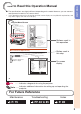
Introduction How to Read this Operation Manual ■ The specifications are slightly different, depending on the model. However, you can connect and operate all models in the same manner. • In this operation manual, the illustration and the screen display are simplified for explanation, and may differ slightly from the actual display. Using the Menu Screen RETURN button • Press RETURN to return to the previous screen when the menu is displayed.
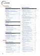
Contents Preparing Introduction How to Read this Operation Manual ......3 Contents .................................................4 IMPORTANT SAFEGUARDS ..................6 How to Access the PDF Operation Manuals..............................................11 Accessories ..........................................12 Part Names and Functions ...................13 Operating with the Remote Control......37 Side View ............................................... 13 Top View ...............................
Setting Auto Power Off Mode ................. 54 Setting No Operation Off Mode .............. 54 Setting the Power Save Mode (Economy Mode) ................................. 54 Setting One Touch Play, System Standby and Input Name ..................... 55 Turning LED Off ...................................... 56 Setting the Demo Mode ......................... 56 Fan Mode Setting ................................... 56 Memory Menu ........................................ 56 Returning to the Default Settings .
IMPORTANT SAFEGUARDS CAUTION: Please read all of these instructions before you operate this product and save these instructions for later use. Electrical energy can perform many useful functions. This product has been engineered and manufactured to assure your personal safety. BUT IMPROPER USE CAN RESULT IN POTENTIAL ELECTRICAL SHOCK OR FIRE HAZARDS. In order not to defeat the safeguards incorporated in this product, observe the following basic rules for its installation, use and servicing. 1.
Do not overload wall outlets, extension cords, or integral convenience receptacles as this can result in a risk of fire or electric shock. 16. Object and Liquid Entry Never push objects of any kind into this product through openings as they may touch dangerous voltage points or short-out parts that could result in a fire or electric shock. Never spill liquid of any kind on the product. 17.
Observe the following safeguards when setting up your projector. Caution concerning the lamp unit ■ Potential hazard of glass particles if lamp ruptures. In case of lamp rupture, contact your nearest Sharp Authorized Projector Dealer or Service Center for replacement. See “Regarding the Lamp” on page 78.
Using the projector in other countries ■ If you are not to use the projector for a long time or before moving the projector, make certain you unplug the power cord from the wall outlet, and disconnect any other cables connected to it. ■ Do not carry the projector by holding the lens. ■ When storing the projector, ensure you attach the lens cover to the projector. ■ Do not expose the projector to direct sunlight or place next to heat sources.
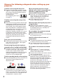
Observe the following safeguards when using the 3D Glasses. Prevention of accidental ingestion Using the 3D Glasses ■ Keep the batteries and band accessory out of the reach of small children. Small children can accidentally swallow these parts. – If a child accidentally swallows any of these parts, seek immediate medical attention. ■ Parents/guardians should monitor children’s viewing habits to avoid their prolonged use without rest periods. ■ Use only the 3D Glasses recommended for this product.
Introduction How to Access the PDF Operation Manuals PDF operation manuals in several languages are included in the CD-ROM. To utilize these manuals, you need to install Adobe® Reader ® on your computer (Windows® or Macintosh®). Please download Adobe® Reader ® from the Internet (http://www.adobe.com). Accessing the PDF Manuals For Windows®: Insert the CD-ROM in the CD-ROM drive. Double click the “My Computer” icon. Double click the “CD-ROM” drive.
Accessories Supplied accessories Two R-6 batteries (“AA” size, UM/SUM-3, HP-7 or similar) Two pairs of 3D Glasses*1 Remote control IR emitter cable IR emitter Power cord*2 (1) For U.S. and Canada, etc. (6' (1.8 m)) (2) (3) For Europe, except U.K. (6' (1.8 m)) For Australia, New Zealand and Oceania (6' (1.8 m)) *1 See pages 64 to 66 for details of the 3D Glasses and their accessories.
Introduction Part Names and Functions Numbers in Z refer to the main pages in this operation manual where the topic is explained. 1 2 3 4 5 6 7 8 9 10 11 14 15 16 Side View 2 LENS button For toggling the menu screens for adjustments of the lens (LENS SHIFT, FOCUS, ZOOM, etc.). 3 RETURN button 42 For returning to the previous menu screen during menu operations. 4 ENTER button 42 For setting items selected or adjusted on the menu.
Part Names and Functions (Continued) 1 5 2 6 3 4 7 8 9 10 11 12 13 Rear View (Terminals) 1 COMPUTER/COMPONENT input terminal 23, 25 Terminal for computer RGB and component signals. 2 Component (YPB (CB)PR (CR)) terminals 23 Terminals for connecting video equipment with component output terminal. 3 HDMI terminals 23, 24 Terminals for HDMI input. 4 LAN terminal 27 Terminal for controlling the projector using a computer via network.
1 10 2 3 11 4 13 5 6 7 8 9 10 11 12 13 14 12 15 14 19 20 21 16 15 17 18 1 2 3 4 5 6 7 ON button 28 For turning the power on. STANDBY button 28 For putting the projector into the Standby mode. CONTRAST, BRIGHTNESS, COLOR and TINT buttons 37 For adjusting the contrast, brightness, color and tint. HDMI 1/2, COMPONENT and COMPUTER buttons 35 For switching to the respective input modes. PICTURE MODE button 37 For displaying the Picture Mode list.
Part Names and Functions (Continued) Inserting the Batteries 1 Pull down the tab on the cover and remove the cover towards the direction of the arrow. 2 Insert the batteries. 3 Insert the upper tab of the cover into the opening, and lower the cover until it clicks in place. • Insert the batteries making sure the polarities correctly match the m and n marks inside the battery compartment. Incorrect use of the batteries may cause them to leak or explode.
Introduction Usable Range Remote control sensor The remote control can be used to control the projector within the ranges shown in the illustration. Note • Another remote control sensor is located on the rear of the projector. (See pages 13 and 14.) • The signal from the remote control can be reflected off a screen for easy operation. However, the effective distance of the signal may differ depending on the screen material.
Easy Start This section shows the basic operation (projector connecting with video equipment). For details, see the page described below for each step. Setup and Projection In this section, connection of the projector and video equipment is explained using one example.
4. Adjust the angle Adjust the projector angle: • Shift the lens horizontally and vertically. 1 Press H&V SHIFT on the remote control. 2 Press P, R, O or Q on the remote control. • Adjust the projector angle by rotating the adjustment feet. Easy Start BPP. 29, 30 5. Adjust the focus and the zoom 1 2 Press FOCUS +/– on the remote control to adjust the focus. Press ZOOM +/– on the remote control to adjust the zoom. BP. 30 6.
Setting Up the Projector Video Setup If using this projector outside the U.S.A., please change setting to “0 IRE” in Video Setup. (See page 50.) Setting Up the Projector For optimal image quality, position the projector perpendicular to the screen with the projector's feet flat and level. Doing so will eliminate the need for Keystone correction and provide the best image quality. (See pages 31 to 34.
Screen Size and Projection Distance When using a wide screen (16:9): In case of displaying the 16:9 picture on the whole of the 16:9 screen Picture (Screen) size Projection distance [L] Width Height Minimum [L1] Diag. [x] 500" (1270 cm) 1107 cm (436") 623 cm (245") 15.7 m (51' 7") 400" (1016 cm) 886 cm (349") 498 cm (196") 12.6 m (41' 4") 300" (762 cm) 664 cm (261") 374 cm (147") 9.4 m (31' 0") 250" (635 cm) 553 cm (218") 311 cm (123") 7.9 m (25' 10") 200" (508 cm) 443 cm (174") 249 cm (98") 6.
Setting Up the Projector (Continued) Projection (PRJ) Mode The projector can use any of the 4 projection modes shown in the diagram below. Select the mode most appropriate for the projection setting in use. (You can set the PRJ mode in “SCRADJ” menu. See page 53.
Connecting the Projector to Other Equipment Before connecting, ensure that the power cord of the projector is unplugged from the AC outlet and turn off the equipment to be connected. After making all connections, turn on the projector and then the other pieces of equipment. When connecting a computer, ensure that it is the last equipment to be turned on after all the connections are made. • For more details of connection and cables, refer to the operation manual of the connecting equipment.
Connecting to Video Equipment Before connecting, be sure to unplug the power cord of the projector from the AC outlet and turn off the devices to be connected. After making all connections, turn on the projector and then the other devices. Connecting Equipment with HDMI Output Terminal to the HDMI Terminal on the Projector For video connection, use a cable that conforms to HDMI standards. Using cables that do not conform to HDMI standards may result in a malfunction.
Connecting to a Computer Ensure that the computer is the last device to be turned on after all the connections are made. Connecting to a computer using the RGB cable Computer To RGB output terminal To COMPUTER/COMPONENT terminal RGB cable (commercially available) Connections Note • See page 81 “Compatibility Chart” for a list of computer signals compatible with the projector. Use with computer signals other than those listed may cause some of the functions to not work.
Controlling the Projector by a Computer When the RS-232C terminal on the projector is connected to a computer with an RS-232C serial control cable (cross type, commercially available), the computer can be used to control the projector and check the status of the projector. Refer to the “SETUP MANUAL” contained on the supplied CD-ROM for “RS-232C Specifications and Commands”.
When connecting to the LAN terminal using a LAN cable LINK LED (green) Illuminates when linked. TX/RX LED (yellow) Illuminates when transmitting/receiving data. * To ensure safety, do not connect the LAN terminal with any cables that may cause excessive voltage such as a telephone line. Hub or Computer To LAN terminal Connections LAN cable (Category 5 type, commercially available) Note • When connecting to a hub, use a straight-through Category 5 (CAT.5) type cable (commercially available).
Turning the Projector On/Off Info Turning the Projector On Note that the connections to external equipment and power outlet should be done before performing the operations written below. (See pages 23 to 27.) • English is the factory default language. If you want to change the on-screen display to another language, change the language according to the procedure on page 53. STANDBY/ON button Press STANDBY/ON on the projector or ON on the remote control.
Image Projection Shifting the Lens In addition to the zoom function and adjustment of projection angle using the adjustment feet, you can adjust the position of the projection using the lens shift function. This is a useful function in cases such as when the screen cannot be moved. When moving upward or downward When moving in the left and right direction ge le ran ge Adjustab Adjustable ran Adjustable range Adjustable range • The adjustable range is shown below.
Image Projection (Continued) Using the Adjustment Feet • When the position of the projected image cannot be adjusted with the lens shift function, use the adjustment feet to adjust the projected angle. • The height of the projector can be adjusted using the adjustment feet when the screen is located higher than the projector, the screen is inclined or when the installation site is slightly inclined. • Install the projector so that it is as perpendicular to the screen as possible.
Correcting Trapezoidal Distortion When the image is projected either from the top or from the bottom towards the screen at an angle, the image becomes distorted trapezoidally. The function for correcting trapezoidal distortion is called Keystone Correction. There are three types of the Keystone Correction.
Image Projection (Continued) GEOMETRIC ADJUSTMENT 1 Press KEYSTONE. 2 Press P/R to select “GEOMETRIC ADJUSTMENT”, and then press ENTER. 3 Press P, R, O or Q to move the position for the upper left of the image. ROn-screen display • The KEYSTONE MODE list appears. (See page 31.) GEOMETRIC ADJUSTMENT H&V KEYSTONE ADJUST NEXT RESET Geometric Adjustment Upper Left 4 Press ENTER to set the position.
H&V KEYSTONE 1 Press KEYSTONE. ROn-screen display • The KEYSTONE MODE list appears. (See page 31.) H&V KEYSTONE Press P/R to select “H&V KEYSTONE”, and then press ENTER. 3 Press P or R to parallelize the left and right sides of the projected image. 4 Press O or Q to parallelize the upper and lower sides of the projected image. 5 Press KEYSTONE to set the position.
Image Projection (Continued) SPHERE 1 Press KEYSTONE. ROn-screen display • The KEYSTONE MODE list appears. (See page 31.) SPHERE 34 2 Press P/R to select “SPHERE”, and then press ENTER. 3 Press P/R/O/Q to adjust the sphere correction. 4 Press KEYSTONE to set the position.
Switching the Input Mode Select the appropriate input mode for the connected equipment. Press HDMI 1/2, COMPONENT or COMPUTER on the remote control to select the input mode. HDMI 1/2, COMPONENT and COMPUTER buttons ■ When you select the input mode with INPUT R/P on the projector: • When R/P is pressed, the INPUT list appears. While the INPUT list is displayed, follow the procedure below to switch the input mode.
Image Projection (Continued) Resize Mode This function allows you to modify or customize the Resize mode to enhance the input image. Depending on the input signal, you can choose a desired image. Press RESIZE on the remote control or on the projector. • See page 51 for setting on menu screen. RESIZE button RESIZE Output screen image NORMAL The image is displayed with the original aspect ratio.
Operating with the Remote Control Selecting the Picture Mode CONTRAST, BRIGHTNESS, COLOR and TINT buttons IRIS 1/2 buttons You can select the appropriate Picture mode for the projected image, such as movie or video game. 1 Press PICTURE MODE to display the Picture Mode list. 2 Press P/R to select the appropriate picture mode, and then press ENTER.
Operating with the Remote Control (Continued) Switching the Iris Setting This function controls the quantity of the projected light and the contrast of the image. Press IRIS 1 or 2. • Each time the button is pressed while the display is on, the mode changes in the following order: ■ IRIS 1 High Brightness ■ IRIS 2 On Off High Contrast Note • For details, see page 45. Auto Sync (Auto Sync Adjustment) Auto Sync function works when detecting input signal after the projector turns on.
Menu Items The following shows the items that can be set in the projector.
Menu Items (Continued) “Signal adjustment (SIG-ADJ)” menu Main menu SIG-ADJ Page 49 Sub menu Clock -150 +150 Phase -30 +30 H-Pos -150 +150 V-Pos -60 +60 “Screen adjustment (SCR-ADJ)” menu Main menu SCR-ADJ Page 51 Sub menu Resize Page 51 V-Image Shift -30 Reset Normal 16:9 CinemaZoom Zoom14:9 SmartZoom Native +30 Page 51 Page 49 Trigger Page 49 Anamorphic Auto Sync [On/Off] Page 50 Video Setup Page 50 Dynamic Range Page 50 Signal Info Page 50 Overscan [On/Off] Auto RGB YPbPr 0
“Projector adjustment (PRJ-ADJ)” menu Main menu PRJ-ADJ Page 54 Sub menu Page 54 Page 54 Sub menu Main menu Network Auto Power Off [On/Off] No Operation off “Network” menu Page 58 Off 1Hour 2Hours 4Hours 6Hours Password [Enable/Disable] Page 58 DHCP Client [On/Off] Page 59 TCP/IP Economy Mode [On/Off] Page 54 Reset Network Setting Page 59 One Touch Play [On/Off] System Standby [On/Off] Restart Network Page 59 Input Name Page 55 IP Address Page 60 LED [On/Off] MAC Address Page 56 P
Using the Menu Screen RETURN button • Press RETURN to return to the previous screen when the menu is displayed. ENTER button Adjustment buttons (P/R/O/Q) MENU button MENU button Adjustment buttons (P/R/O/Q) ENTER button RETURN button • Press RETURN to return to the previous screen when the menu is displayed. Menu Selections (Adjustments) Example: Adjusting “Bright”. • This operation can also be performed by using the buttons on the projector. 1 Press MENU.
3 Press P or R and select “Bright” to adjust. • The selected item is highlighted. SIG Picture Picture Mode Contrast Bright Color Tint Sharp Red Gain Green Gain Blue Gain CLR Temp IRIS1 (Manual) IRIS2 (Auto) Eco+Quiet Advanced Reset SCR PRJ Standard Net. 0 0 0 0 0 0 0 0 0 High Brightness On Off SEL./ADJ. RETURN ENTER END Items to be adjusted To adjust the projected image while watching it Press ENTER. • The selected item (e.g. “Bright”) is displayed by itself at the bottom of the screen.
Picture Adjustment (“Picture” Menu) Menu operation n Page 42 Picture SIG Picture Mode Contrast Bright Color Tint Sharp Red Gain Green Gain Blue Gain CLR Temp IRIS1 (Manual) IRIS2 (Auto) Eco+Quiet Advanced Reset SEL./ADJ. RETURN SCR PRJ Standard Net. 0 0 0 0 0 0 0 0 0 High Brightness On Off ENTER END IRIS2 (Auto) Eco+Quiet Advanced Gamma Custom Gamma C.M.S.1 C.M.S.2 Bright Boost Film Mode Color Enhance Detail Enhance DNR MNR Reset SEL./ADJ.
Menu operation n Page 42 2 Adjusting the Image Adjustment items Contrast Bright Color ? button _ button For less contrast. For less brightness. For less color intensity. Tint For making skin tones purplish. Sharp For less sharpness. Red Gain For making images less reddish. Green Gain For making images less greenish. Blue Gain For making images less bluish. CLR Temp For making images slightly more reddish (slightly warmer colors). For more contrast. For more brightness. For more color intensity.
Picture Adjustment (“Picture” Menu) (Continued) Menu operation n Page 42 7 Custom Gamma The Custom Gamma function can be used when “Picture Mode” is set to “User1” or “User2”. You can adjust the gamma curve and save your custom setting. Adjust it to suit the picture brightness. 1 Press P/R to select “Custom Gamma” on the gamma adjustment screen, and then press Q. 5 Press ENTER to display the confirmation screen. Use P/R to select “Save” and press ENTER.
Menu operation n Page 42 • If there is data for the stored corrected color, the C.M.S. color adjustment screen is displayed. (Go to step 3.) C.M.S.1 Select Color Hue Saturation Value Effect C.M.S.1 Reset Return C.M.S. color adjustment screen: Selectable Description items Select Starts over the selection of the Color color to be corrected. Hue Sets the hue of the main colors. 0 0 0 0 On Saturation Value SEL./ADJ. RETURN 2 ENTER END Effect*1 C.M.S.1*2 (or C.M.S.
Picture Adjustment (“Picture” Menu) (Continued) Menu operation n Page 42 9 Adjusting the Bright Boost Bright Boost uses Texas Instruments’ Bright Boost technology. The image becomes brighter while the color reproduction is kept at a high level. Selectable items Description On The Bright Boost function is activated. Off The Bright Boost function is not activated. Note • Set “DNR” to “Off” in the following cases: - When the image is blurry. - When the contours and colors of moving images drag.
Computer Image Adjustment (“SIG-ADJ” Menu) Menu operation n Page 42 Pict. SIG-ADJ Clock Phase H-Pos V-Pos Reset Resolution Auto Sync Signal Type Video Setup Dynamic Range * SCR 0 0 0 0 PRJ Net. Setting the Resolution Ordinarily, the type of input signal is detected and the correct resolution mode is automatically selected. However, for some signals, the optimal resolution mode in “Resolution” in the “SIGADJ” menu may need to be selected to match the computer display mode.
Computer Image Adjustment (“SIG-ADJ” Menu) (Continued) Menu operation n Page 42 Signal Type Setting When using an input mode of HDMI1, HDMI2, or COMPUTER, set the signal type to the corresponding input signal type (RGB or YPbPr). Selectable items Auto Description Automatically selects the appropriate input signal between RGB and YPbPr. RGB Set when RGB signals are received. YPbPr Set when YPbPr signals are received.
Adjusting the Projected Image (“SCR-ADJ” Menu) Menu operation n Page 42 Pict. SIG Resize V-Image Shift Trigger Anamorphic Overscan Black Mask CBNR OSD Display OSD Brightness Background Menu Position PRJ Mode Language SEL./ADJ. RETURN SCR-ADJ PRJ Normal Net. 3 Trigger 0 Off Off On 0 Off On Standard Logo Upper Left Front English This function allows you to set whether to output a control signal (12V DC) that is output from the trigger terminal to a triggersupported screen or anamorphic lens.
Adjusting the Projected Image (“SCR-ADJ” Menu) (Continue) Menu operation n Page 42 5 Adjusting the Overscan This function allows you to adjust the Overscan area (display area). Selectable items Description On The input area is displayed without screen edges. Off The whole input area is displayed. 7 CBNR This function reduces the color break noise. Selectable items Description On The CBNR function is activated. Off The CBNR function is not activated.
Menu operation n Page 42 T Selecting the Menu Screen Position Select “Menu Position” in the “SCR-ADJ” menu and the desired position for the menu screen. Selectable items Description Center Displayed on the center of the image. Upper Right Displayed on the upper right of the image. Lower Right Displayed on the lower right of the image. Upper Left Displayed on the upper left of the image. Lower Left Displayed on the lower left of the image.
Adjusting the Projector Function (“PRJ-ADJ” Menu) Menu operation n Page 42 Pict. SIG Auto Power Off No Operatin Off Economy Mode One Touch Play System Standby Input Name LED Demo Mode Fan Mode Memory Menu All Reset SCR PRJ-ADJ On Off Off Off Off Net. Off Off Normal Lamp Timer (Life) X h XX min ( XX% ) SEL./ADJ. RETURN This function automatically switches the projector to Standby mode if there is no operation.
Menu operation n Page 42 Setting One Touch Play, System Standby and Input Name When a Sharp product equipped with Consumer Electronics Control (HDMI CEC) is connected to the projector with an HDMI cable, you can use the linked function with HDMI CEC (“One Touch Play” and “System Standby”). Note • The CEC function may not work with some CEC devices. (When the projector is connected to a non-Sharp product, the CEC function may not work.
Adjusting the Projector Function (“PRJ-ADJ” Menu) (Continued) Menu operation n Page 42 5 Turning LED Off LEDs (indicators) on the projector can be turned off when they are disturbing the projection. Selectable items Description On LEDs are turned on. Off LEDs are turned off while the projector is in operation. (LEDs turn on while the projector is in the Standby mode, warming up or indicating problems.
Menu operation n Page 42 a Clear Memory Select the item where the settings you want to erase are stored. In this case, the memory name you have changed returns to the default setting. Note • Selecting “All Clear” erases all the stored settings. a Memory Lock Selectable items Description On Protects the stored memories. Off Does not protect the stored memories. Returning to the Default Settings Use “All Reset” to initialize all the adjustments you have made to the default settings.
Setting Up the Projector Network Environment (“Network” Menu) Menu operation n Page 42 Pict. SIG SCR Password DHCP Client TCP/IP Reset Network Setting Restart Network IP Address MAC Address Projector PRJ Network Disable Off XXX.XXX.XXX.XXX XX:XX:XX:XX:XX:XX XX-XXXX SEL./ADJ. RETURN ENTER END 1 Setting a Password If you do not want others to change the setting for the “Network” menu, set a password. a Setting a Password 1 • The screen for entering the password appears.
Menu operation n Page 42 2 DHCP Client Setting Selectable items Factory default setting: 192.168.150.002 Enter an IP address appropriate for the network. Subnet Mask Factory default setting: 255.255.255.000 Set the subnet mask to the same as that of the computer and equipment on the network. Gateway Factory default setting: 000. 000. 000. 000 * When not in use, set to “000. 000. 000. 000”. Connect the LAN cable before turning the projector on. If not, the DHCP Client function does not work.
Setting Up the Projector Network Environment (“Network” Menu) (Continued) Menu operation n Page 42 6 Confirming the Projector Information You can confirm the following items. Selectable items IP Address Description The IP address of the projector is displayed. MAC Address The MAC address of the projector is displayed. Projector The projector name is displayed. Note • For information on how to change the projector name, see “SETUP MANUAL” contained in the supplied CD-ROM.
Enjoying 3D Image Viewing CAUTION: Before viewing 3D images, please read this section carefully. You can use special 3D Glasses to watch 3D-supported images on this projector. ■ You can enjoy 3D images by viewing the video images through the 3D Glasses supplied with the projector or through optional 3D glasses sold separately.
Enjoying 3D Image Viewing (Continued) Precautions on viewing 3D images As you get more comfortable viewing 3D images: ■ When viewing 3D images continuously, be sure to take a break periodically to prevent eye strain. ■ Take regular breaks, at least 5 to 15 minutes after every 30 to 60 minutes of 3D viewing. * Based on the guidelines issued by the 3D Consortium revised December 10, 2008. ■ View 3D images at the appropriate distance from the screen.
WARNING ■ The following people should limit stereoscopic 3D viewing: – Children under 6 years of age (to protect the eye growth process) – People with a history of photosensitivity – People with heart disease – People in poor health – People who are sleep deprived – People who are physically tired – People under the influence of drugs or alcohol ■ Epilepsy A small percentage of the population may experience epileptic seizures when viewing certain types of images that contain flashing patterns of light.
Enjoying 3D Image Viewing (Continued) Supplied Accessories for the 3D Glasses Make sure the following accessories are provided with the 3D Glasses. Two sets of 3D Glasses are provided. 3D Glasses (×2) Pages 65, 66, 68 and 69 3D Glasses band * (×2) Page 66 Nose pad * (Large ×2, small ×2) Page 66 Glasses case (×2) Cleaning cloth (×2) Precision screwdriver (Phillips ×2, slotted ×2) Page 65 * Use the 3D Glasses band and nose pad as needed.
2 Before Using the 3D Glasses Before using the 3D Glasses for the first time, remove the insulating sheet attached to them. Remove the button cell battery. Place the tip of the slotted precision screwdriver into the opening between the button cell and the socket. Lift up the button cell while taking care not to get the screwdriver caught on the metal latch. 1 2 3 When the battery comes loose from the socket, pick it out with your fingers.
Enjoying 3D Image Viewing (Continued) Attaching the Nose Pad Attach either of the supplied nose pads as needed (such as when the glasses do not fit properly). The glasses come with a large and small nose pad. Using the 3D Glasses Turning On/Off the Power Turn on the power of the 3D Glasses. • Press the power button for at least 2 seconds. • The LED light blinks 3 times. Turn off the power on the 3D Glasses. • Press the power button for at least 2 seconds. • The LED light lights for 2 seconds.
Connecting the IR Emitter to the Projector 1 Install the IR emitter unit to the stand. Loosen 2 Insert the IR emitter cable to the unit. 3 Connect the IR emitter and the projector. Fasten To 3D SYNCHRO terminal IR emitter cable 4 Position the IR emitter. Useful Features • 3D images are intended to be viewed while facing the screen from the front. • Position the IR emitter so that the 3D Glasses can easily receive the infrared signals while viewing the screen from the front.
Enjoying 3D Image Viewing (Continued) 3D MENU button Adjustment buttons (P/R/O/Q) ENTER button Note 3D MENU button • The screen may temporarily become black when the projector is trying to detect a 3D image signal and when switching from 3D to 2D mode. 3D ON/OFF button Viewing 3D Images Receiving a 3D Image Signal That Can Be Detected Automatically The image signal may contain a 3D identification signal.
Receiving a 3D Image Signal That Cannot Be Detected Automatically 1 Press 3D MENU. 2 Press P/R to select “3D”. 3 Press O/Q to select “On” or “Off”. Ending 3D Image Viewing 1 Press 3D ON/OFF during the 3D mode. 2 Take off the 3D Glasses and turn off the power. • The 3D MENU screen is displayed. • To view in 3D mode: Select “On”, and then go to step 4. • Refer to “Setting the 3D Format Menu” on page 71 for supported 3D signals and formats.
Enjoying 3D Image Viewing (Continued) 3D Depth Adjust 3D Settings (“3D MENU”) 3D MENU 3D 3D Format 3D Depth Adjust 3D Auto Change Viewing Time Info Invert On Auto 0 Yes Yes You can adjust the stereoscopic effect of 3D image. ? button For less stereoscopic effect. _ button For greater stereoscopic effect. Note 3D You can switch between 2D and 3D mode. Selectable items Description On Projects 3D images. Off Projects 2D images instead of 3D images.
Setting the 3D Format Menu Select the appropriate 3D format for viewing while referring to the table below.
Enjoying 3D Image Viewing (Continued) Note • These 3D Glasses can only be used with Sharp 3D-compatible LCD TVs or projectors that use infrared control technology. 3D Glasses lenses • Do not apply pressure to the lenses of the 3D Glasses. Also, do not drop or bend the 3D Glasses. • Do not scratch the surface of the lenses of the 3D Glasses with a pointed instrument or other object. Doing so may damage the 3D Glasses and reduce the quality of the 3D image.
Specifications – 3D Glasses Model AN-3DG10 Lens type Liquid crystal shutter Power supply 3 V DC Battery Lithium button battery (CR2032 × 1) Battery life Approx. 75 hours of continuous use Dimension (W x H x D) 6 13/16 × 1 7/8 × 6 45/64 inch (172.7 × 47.5 × 170.0 mm) Weight 0.2 lbs./65.0 g (including the lithium button battery) Operating temperature 50°F to 104°F (10°C to 40°C) (The 3D Glasses cannot operate fully at extreme high or low temperatures.
Enjoying 3D Image Viewing (Continued) Specifications – IR Emitter Dimension [W × H × D] 5 3/32 × 2 21/64 × 5 23/32 inch (129 × 59 × 137 mm) Weight (approx.) 0.4 lbs. (170 g) Dimensions 15° 2 21/64 (59) 63 /64 (25) 90° 3 19/32 (91) 4 27/64 (112) 3 3 5 /32 (129) 5 /32 (129) Effective Distance The 3D Glasses can receive infrared signals sent from the IR emitter within the range indicated in the diagram. Operating range (Distance from the IR emitter): Approx. 32.8 ft (10.
Maintenance Cleaning the projector ■ Ensure that you have unplugged the power cord before cleaning the projector. ■ The cabinet as well as the operation panel is made of plastic. Avoid using benzene or thinner, as these can damage the finish on the cabinet. ■ Do not use volatile agents such as insecticides on the projector. Do not attach rubber or plastic items to the projector for long periods. The effects of some of the agents in the plastic may cause damage to the quality or finish of the projector.
Maintenance Indicators ■ The warning lights (power indicator, lamp indicator and temperature warning indicator) on the projector indicate problems inside the projector. ■ If a problem occurs, either the temperature warning indicator or the lamp indicator will illuminate red, and the projector will enter Standby mode. After the projector has entered Standby mode, follow the procedures given below.
Maintenance indicator Normal Temperature warning indicator Lamp indicator Power indicator Off Green on (Green blinks when the lamp is warming up.) Green on/ Red on Green blinks (Cooling) Abnormal Problem Cause Possible Solution • Temperatures around the projector are high. • Blocked air intake • Use the projector in an area with a temperature of lower than 95°F (+35ºC). • Relocate the projector to an area with proper ventilation. (See page 8.
Regarding the Lamp Lamp ■ It is recommended that the lamp (sold separately) be replaced when the remaining lamp life becomes 5% or less, or when you notice a significant deterioration in the picture and color quality. The lamp life (percentage) can be checked with the on-screen display. (See page 57.) ■ Purchase a replacement lamp of type AN-K30LP from your place of purchase, nearest Sharp Authorized Projector Dealer or Service Center. IMPORTANT NOTE TO U.S.
Removing and Installing the Lamp Unit Warning! • Do not remove the lamp unit from the projector right after use. The lamp and parts around the lamp will be very hot and may cause burns or injury. Lamp unit AN-K30LP Optional accessory Info • Do not touch the glass surface of the lamp unit or the inside of the projector. • To avoid injury to yourself and damage to the lamp, make sure you carefully follow the steps below. • Do not loosen other screws except for the lamp unit cover and lamp unit.
Regarding the Lamp (Continued) 4 Remove the lamp unit. 5 Insert the new lamp unit. 6 Replace the lamp unit cover. Securing screws • Loosen the securing screws from the lamp unit. Hold the lamp unit by the handle and pull it in the direction of the arrow. At this time, keep the lamp unit horizontal and do not tilt it. Handle • Press the lamp unit firmly into the lamp unit compartment. Fasten the securing screw. • Align the tab on the lamp unit cover (1) and close it (2).
Compatibility Chart Computer x Multiple signal support Horizontal Frequency: 15–110 kHz, Vertical Frequency: 43–85 Hz, Pixel Clock: 12–170 MHz x Compatible with sync on green and composite sync signals (TTL level) PC/MAC Mode Resolution ✔ ✔ ✔ ✔ ✔ ✔ ✔ ✔ ✔ ✔ ✔ ✔ ✔ ✔ ✔ ✔ ✔ ✔ ✔ ✔ ✔ ✔ ✔ ✔ ✔ ✔ ✔ ✔ ✔ ✔ ✔ ✔ ✔ ✔ ✔ ✔ ✔ ✔ ✔ ✔ 1400 × 1050 WSXGA+ 1600 × 900 1680 × 1050 1920 × 1080*1 1920 × 1080*2 67.5 60 ✔ 640 × 480 832 × 624 1024 × 768 1152 × 870 34.9 49.7 60.2 68.
Compatibility Chart (Continued) DTV Horizontal Frequency (kHz) 15.7 Vertical Frequency (Hz) 60 Analog Support Horizontal Frequency (kHz) 28.1 Vertical Frequency (Hz) 50 Analog Support Digital Support 31.5 60 ✔ ✔ ✔ 33.8 60 ✔ ✔ ✔ 1080I 1080P 540P 33.8 60 27.0 24 576I 576P 15.6 ✔ 50 ✔ 1080P 28.1 25 ✔ 31.3 50 ✔ ✔ 1080P 33.8 30 720P 37.5 50 ✔ ✔ 1080P 56.3 50 ✔ ✔ 720P 45.0 60 ✔ ✔ 1080P 67.
Troubleshooting Problem No picture or projector does not start Check Page x Projector power cord is not plugged into the wall outlet. 27 x Power to the external connected devices is off. – x The selected input mode is wrong. 35 x Cables are incorrectly connected to the projector. 23-27 x Remote control battery has run out. 16 x External output has not been set when connecting notebook computer. – x The lamp unit cover is not installed correctly.
Troubleshooting (Continued) Problem Check Page The black levels of the image show banding or appear faded when HDMI1 or 2 is selected. x Make adjustments that result in the best picture quality in the “Dynamic Range” setting. 50 Picture is too bright and whitish. x Image adjustments are incorrectly set. 45 x The lens cover is not attached correctly. 13 x When temperature inside the projector increases, the cooling fan runs faster. – x The lamp indicator is illuminating in red. Replace the lamp.
Problem Check Page x Switch to 3D mode. 68-70 x Is “3D Auto Change” set to “No”? Press 3D ON/OFF to switch to 3D mode. 70 x If “3D Auto Change” is set to “Yes” but no 3D images are displayed, check the display format of the content being viewed. Some 3D image signals may not be recognized as 3D images automatically. Press 3D MENU to select the appropriate display format for the 3D image. 70, 71 x The IR emitter is not correctly connected to the projector.
For SHARP Assistance If you encounter any problems during setup or operation of this projector, first refer to the “Troubleshooting” section on pages 83 to 85. If this operation manual does not answer your question, please contact the SHARP Service departments listed below. U.S.A. Sharp Electronics Corporation 1-888-GO-SHARP (1-888-467-4277) lcdsupport@sharpsec.com http://www.sharpusa.com Canada Sharp Electronics of Canada Ltd. (905) 568-7140 http://www.sharp.
Specifications Model Display devices Resolution Lens Input terminals Output terminals F number Zoom Focus HDMI Computer/Component (mini D-sub 15 pin) Component (3RCA) TRIGGER 3D SYNCHRO LAN (RJ-45) RS-232C (mini DIN 9 pin) Control and communication terminals Projection lamp Rated voltage Rated frequency Input current Power consumption (Eco + Quiet) Off On Power consumption (Economy Mode) Off On Operation temperature Cabinet Dimensions (main body only) [W × H × D] Weight (approx.
88 1 1 /2 (38) 4 11/32 (110) 6 3 1/2 (89) 13 5/16 (338) 21/64 (160.5) M4 M4 M4 M4 M4 M4 M4 1 5/ 8 (41.25) 2 61/64 (75) 3 3/4 (95) 11 63/64 (304) 7 31/64 (190) 7 31/64 (190) 2 9/64 (54) (10) 25/64 5 5/16 (134.5) 4 33/64 (114.5) 2 25/64 (60.5) 7 63/64 (202.5) 3 3/4 (95) 2 59/64 (74) 16 (406.
Index 16:9···················································································36 3D Auto Change ·······························································70 3D Depth Adjust ·······························································70 3D Format·········································································70 3D Glasses ································································· 64-66 3D MENU ·········································································70 3