Digital Video Switcher HS-500 Error! INSTRUCTION MANUAL Http://www.datavideo-tek.
Table of Contents Warnings and Precautions Warnings and Precautions Radio and Television Interference Warranty Disposal 3 3 3 4 4 Introduction Introduction Product overview Features 4 4 5 5 Packing List 5 HS-500 General Operation 6 Some General Notes on Installation Setting Up Connecting Video Sources and Power Cable 6 6 7 SE-500 10 Front panel Rear panel Selecting video input formats and adjusting audio levels Selecting video output format Using Video and Audio Monitors Cutting between sources
SE-500 Troubleshooting / FAQ No power No image at output / S-Video output is black and white Audio clipping Frozen image at output Image distortions etc How does RS 232 work in practice 34 34 34 34 34 34 34 SE-500 Appendix RS-232 Remote Control Commands MIDI Control Commands Tally Pinouts cross reference between the TLM-404 & the SE-500 Specifications 35 35 40 42 43 TLM-702 44 Front Panel Rear Panel Specifications 44 45 46 Useful Accessories 48 Service and Support 50 2
Warnings and Precautions 1. Read all of these warnings and save them for later reference. 2. Follow all warnings and instructions marked on this unit. 3. Unplug this unit from the wall outlet before cleaning. Do not use liquid or aerosol cleaners. Use a damp cloth for cleaning. 4. Do not use this unit in or near water. 5. Do not place this unit on an unstable cart, stand, or table. The unit may fall, causing serious damage. 6.
3. Connect the equipment into an outlet on a circuit different from that to which the receiver is connected. If necessary, consult your dealer or an experienced radio/TV technician for help and/or additional suggestions. N.B.: Changes or modifications not expressly approved by the party responsible for compliance could void the user’s right to operate this equipment. Peripherals used in conjunction with this equipment must be connected via shielded interface cables.
Features Digital Processor, high image quality Four inputs of S-Video (Y/C) or Composite video Quad video preview monitor output with tally & transition indicators on screen Built in Dual 7” Monitors (TLM-702) Optional YUV output – via supplied breakout cable Quad, Split, PIP, Wipe, and Fade digital video effects T-Bar control of digital video effect transitions Color processor for video correction RS232 remote control MIDI control interface Tally output Audio mixer with two microphone channels and one auxi
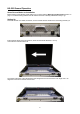
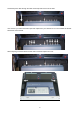
HS-500 General Operation Some General Notes on Installation Before setting up the HS-500, please make sure you have read the Warnings and Precautions section on page 3. The internal wiring between the SE-500 and TLM-702 is already installed and ready to go. Setting Up Place the HS-500 on a stable, flat surface, such as a desk with the handle of the case facing towards you. Ensure that the larger of the two sections, which has the handle attached, is on top. Unlock the two locks and lift the lid.
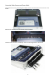
Connecting Video Sources and Power Cable Firstly remove the cover by unscrewing the two thumb screws, this allows easier access to the rear of the SE-500 With the cover removed you can see the rear panel of the SE-500 At the rear of the case there is a cable flap, unlock it so that it hinges down to allow access.
Thread the power cable through the cable access flap and insert it into the PSU. Now connect your video and audio inputs and outputs from your cameras etc. For more details see the SE500 section of this manual. With everything connected switch the SE -500 on and then replace the cover.
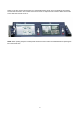
Switch on the two monitors and set them to a comfortable viewing angle. For more details of the monitors see the TLM-702 section. The HS-500 connections use the V1 inputs on both monitors. Make sure that the source switches are both set to V1. NOTE: When packing away the HS-500 please ensure that the monitors are folded flat before replacing the lid on the transit case.
SE-500 SE-500 Front Panel 3 4 5 6 7 8 9 10 2 11 1 15 1. 2. 3. 4. 5. 6. 7. 8. 14 Audio faders Headphone Socket Audio meters Headphone Volume Control Video Effect: Quad Video Effect: Split Video Effect: PIP Video Effect: Freeze 9. 10. 11. 12. 13. 14. 15.
1. Faders: sliders to control audio levels for the Main audio output mix. These Audio Level pots are the first stage in the audio signal path. Analog audio comes in through the 1/4 inch phono jack and RCA connectors on the rear panel see Rear Panel, page 14. 2. Headphones jack: accepts a stereo mini jack plug for stereo headphones. The headphone volume is controlled by the Headphone volume control (4.). 3. Audio Meters: LED style meters, which show the signal strength at the Audio Output.
9. Background: When Background is selected in either the Main or Sub Video Source (13, 14.), and the button is pressed (and the LED is lit except with black color background), repeated presses of the color button cycle through the 8 possible solid backgrounds. For more information, see Background, page 29. 10. Menu: Press and hold the button “BACKGROUND COLOR” for 2 seconds or more, a menu will pop up. You are able to change the camera settings, which include Brightness, Contrast, color, Tint (NTSC only).
16. Transition selectors: These twelve selection buttons determine the transition type and allow for the selection of certain effects that are performed on the selected Main Video Input channel. For more information, see Using Transitions, page 24 and Using Effects, page 27. Tech note: Transcoding is the act of changing video from one format to another, for example, from composite video to S-video. The SE-500 has been designed to perform transcoding, as part of its standard operating procedure.
SE-500 Rear Panel 1a 1b 2a 2c 2b 3 2d 4 5 6 1. Video inputs, Channels 1, 2, 3, 4. 3. RS-232 Control 1a. Composite video input (BNC) 4. Tally Signal out 1b. S-Video (Y/C) input 5. MIDI Control* 7 8 9 10 11 6. Microphone input Ch2 (1/4” jack) 2. Video outputs 2a. Composite video out (BNC) 7. Microphone input Ch1 (1/4” jack) 2b. S-video (Y/C) out 8. Audio inputs (Stereo, RCA connector) 2c. Component (Combine Composite & 9. Two Stereo Audio outputs (RCA) 10.
1. Video In (Channels 1, 2, 3, and 4 are all set up the same way) a. Composite video input: takes a BNC connector from the composite output of a VCR, camera, DVD player, etc. b. S-Video (Y/C) input: takes a standard 4 pin S-video cable from the output of a VCR, camera, DVD player, etc. N.B If S-Video (Y/C) is connected it will be automatically selected in priority over Composite. 2. Video Output. These ports carry the Main video output of the SE-500. a.
8. Audio Inputs: A RCA stereo for a line level auxiliary analog audio source, such as a CD player or tape deck. If you are using more than two sources via an external audio mixer, connect the audio mixer’s line level output to this unbalanced Audio input. 9. Audio Output: A RCA stereo line level analog audio output, carrying the signal present at the output of the audio mixer section (see Controls and Operations, page 20). 10. Power: Switches the unit On / Off. 11.
Selecting video input formats and adjusting audio levels (Numbers refer to the Front Panel illustration above)*. Verify that there is a valid source at each input you’ve connected by using the Main Source Select buttons (13.) to select a channel and view the output on the main monitor. For each input channel (1, 2, 3, 4): connect either a Composite or S-Video source to each channel. For more information please see below.
Dissolving between sources Select the Main Video Source (13.) by pressing the appropriate channel button. The LED for the channel you have selected should be lit and you should see that source on the program monitor. Select the Sub Video Source (14.) you want to dissolve to. The default transition is fade (The LED should be lit when you turn on the switcher. If a different transition is selected at power up, press it to deselect.) Move the T-Bar (11.
PIP effect (7.), which stands for Picture in Picture. As you might guess, this effect requires a Main and Sub Video Source. Assuming you have valid inputs on Channel 1 and 2, select Channel 1 as the Main Source and Channel 2 as the Sub Source. When you engage the effect by pressing the PIP button (and verifying that the LED on the button is lit), on the program monitor you will have Channel 1 as the Main Source and Channel 2 as a smaller window inset. There are two choices for window size.
Controls and Operations Video Source The first thing to do when using the SE-500 is to select the Main and Sub Video Sources. The source you select (by pressing one of the buttons; a bright red LED on the selected button lights for confirmation) on the Main Source bus is what is sent to the Video output. This means that you can perform cuts between sources by simply pressing different buttons.
Color Processor The Color Processor controls work when you press and hold the “Background” (9.) button for 2 seconds or more, which is temporarily displayed at the Preview Output. For more information, please see the “MENU” section. These controls are like picture controls on a video monitor or the proc amp (processing amplifier) controls on a time base corrector. In fact, they are the proc amp controls of one of the SE-500’s 4 internal TBCs.
The most serious, accurate color correction is done with the aid of a waveform monitor/vector scope, a signal analysis instrument (actually a pair of instruments) common in video editing suites, which shows precisely the details of the video signal. With one of these instruments, you can see at a glance (once you know what you are looking for) the most intimate electronic details and irregularities of the video signal.
Audio Inputs, Levels, and Meters (Faders, bus selectors,) Audio Input Level Calibration Procedure The first step in setting up the audio for a session with your SE-500 consists of adjusting the levels on which channel you will be using. Slide the Master fader to Max, and set the other faders to 0.
Using Transitions The SE-500 can do 3 kinds of transitions: cut, fade, and wipe. The cut is a simple switch from one input source to another, and can be accomplished by selecting a source on the Main Source Bus, and then selecting a second one. One source is replaced by the next at the video output. Not flashy, not fancy, nothing to customize, but gets the job done. In fact, if you watch a film or video, paying attention to transitions, you’ll see that the cut is far and away the most often used transition.
List of transitions and parameters (suitable for photocopying) Wipe (works in conjunction with Border controls): 1: Block wipe from center to full screen.
10: Vertical wipe, middle to left and right 11: Horizontal wipe, middle to top and bottom 26
Using Effects The SE-500 is capable of producing a wide variety of digital effects. These falls into 2 categories: single channel and dual channel effects. Single channel effects are produced on the source selected in the Main Video Source bus and need no second video input. Single channel effects include Freeze. For example, select any input channel having a valid signal as the Main Video Input. Press the Freeze button once. You’ll see, on the program monitor, that the source video stops instantly.
Effects: Quad The Quad effect combines 4 input videos into 1 output. When this effect is activated, it shows 4 video sources on 1 single monitor. Each source takes one quarter of the entire screen. Press the button again, and it returns to the previous selected source in full screen. This is a dual channel effect, and cannot be used with any other transitions or effects. Effects: Split This effect will squeeze the Main Video Source and Sub Video Source into a half size screen.
Border These controls are used in conjunction with the Picture in Picture Effect and Wipe transition only, and can only be activated when the Picture in Picture or Wipe control is active. 8 Colors are available for the wipe border: black, blue, magenta, red, green, cyan, yellow and white. See “Background Color” below. (Wipe only). In PIP mode the border can only be white.
Four Camera Shoot: Live Stage Performance / Sporting Event The first example is a typical four-camera shoot. The example is based on a stage performance such as a play or a band, but it could just as easily be slightly modified for other live situations such as sporting events. The four cameras are feeding analogue signals to the SE 500, via Composite or S-Video. It would be possible to use DV cameras by adding a Datavideo DAC 6 to each of the channels that you want to run DV.
Live Conference In this second example we see a typical conference set up. There are two cameras to handle the speaker and the overview, with audience reaction or other action on the stage. Both cameras are analogue, but by adding a DAC 6 to any of the channels it would be possible to use a DV camera. There is a VCR or DVD player cued up with footage to enhance the speaker’s presentation, and a feed from a laptop of a PowerPoint presentation that the speaker will be referencing throughout his speech.
Live Event Mixing: Club VJ / Concert In our final example we are looking at a typical V.J. set up. Increasingly in clubs video images are used to add to the overall effect and atmosphere, they are combined with light displays and other audio / visual effects. In the set up above we see two cameras being used, one on the audience and the second on the V.J, it could just as easily be a second angle of the audience.
Using SE-500 with CG-100 for Titles/Graphics/Logos overlay Using YUV output (with a breakout cable) on SE-500 to communicate with a PC with Decklink SP CG overlay card and CG-100 CG software (page 42) to perform a text overlay for the output video.
Troubleshooting / FAQ No power No image at output / black and white output from S-Video (Y/C) Audio clipping Audio or video feedback Frozen image at output Image distortions How does the RS 232 work in practice No power 1. Check that the power supply is plugged into the SE 500, and to a suitable mains outlet, and that it is switched on. 2. Move the SE-500 to a cooler location and allow the unit time to cool off before powering on again. No image at output / black and white output from S (Y/C) 1. 2.
SE500 RS-232 Remote Control Command VER: 1.01 Release date: 2006/01/19 1. Physical layer 1.1 Control output format: RS-232C 1.2 Communication rate: 57600 BPS 1.3 Data format: 8 bits serial, LSB first, 1 start bit, 1 stop bit, odd parity 1.4 Must delay 100uSEC between 2 bytes 2. Data link layer 2.1 Frame format 1st 2nd Header ID 3rd 4th 5th 6th 7th Length Data0 Data1 Data2 Data3 ,,, ,,, Last-2 Last-1 Chksum_L Chksum_H Last End 1) Header Code consisting of one byte for frame synchronization.
1) The command group 05h (base 16) = SE500 control command 2) The operated refer to section 4. 3.2 Return data format 4th 5th 6th 7th 8th 9th 10th 11th … Command parameter parameter parameter parameter parameter parameter parameter … Status #0 #1 #2 #3 #4 #5 #6 1) The command status 05h=SE500 control command status 2) The parameter refers to section 6. 4. The operated of SE500 control command 5th Operated #0 Mode Code 6th Operated #1 Key code 7th Operated #2 T-bar low 8th Operated #3 T-bar high 4.1.
15h= key_left_bottom_block (wipe) 16h= key_top_block (wipe) 17h= key_bottom_block (wipe) 18h= key_right_block (wipe) 19h= key_left_block (wipe) 1ah= key_horizontal (wipe) 1bh= key_vertical (wipe) 20h= key_border_on 22h= key_background_color 24h= key_speed* 26h = key_PIP 3bh = key_menu 3ch = key_up 3dh = key_down 3eh = key_left 3fh = key_right 40h = key_reset 41h = key_plus 42h = key_minus *Note: Send the key_speed code to the SE500,the speed of effect will be changed follow below rule.
4) The effect No. The value from 0 to 99(63h) Fade effect No. = 0 Wipe effect No.= 0 to 10 Quad effect No.= 0 POP effect No. = 0 to 1 PIP effect No.:bit3 to bit0= x0h to x4h (position) Bit4=0=big size, bit4=1=small size Bit5=0=not shift, bit5=1=shift to close center.
7. EXAMPLE 1) PC control SE500, key command = key_take= 0fh a.) The command stream = F0h,32h,0eh,05h,01h,0fh,,30h,34h,ffh Header=F0h ID=32h Length = 9 bytes=09h Command group=05h Command mode=normal control code=01h Control key code=key_take =0fh checksum= (f0h+32h+09h+05h+01h+0fh) = 40h checksum_low =00h+30h = 30h checksum_high=04h+30h = 34h END =ffh b.
SE500 MIDI Remote Control Command VER: 1.00a Release date: 2005/06/03 1. Physical layer 1.5 Follow the MIDI SPEC. 1.0 1.6 Communication rate: 31250 BPS 1.7 Data format: 8 bits serial, LSB first, 1 start bit, 1 stop bit, none parity 2. Data link layer 2.1 Control messages = MIDI Channel voice messages * Received only if Note Mode is ON * The input of each channel is selected. * Ignored if a non-selectable note message is received. 2.
F5 65 SUB D key F#5 66 PIP key G5 67 SUB BG key G#5 68 Freeze key A5 69 Preview key A#5 70 NC B5 71 TAKE key C6 72 MAIN A key C#6 73 Background color key D6 74 MAIN B key D#6 75 Border key E6 76 MAIN C key F6 77 MAIN D key F#6 78 Speed _1 key G6 79 MAIN BG key G#6 80 Speed_ 2 key A6 81 Change Speed key A#6 82 Speed_ 3 key 4. Example 1.
SE500 Tally Pin Outs Cross Reference VER: 1.
Specifications Video Formats Analog Y/C, Composite CCIR601 NTSC and PAL (PAL and NTSC are separate models) Video Inputs 4 – S (Y/C), Composite Video Output 1 – Quad Video source monitoring (Composite) 2 – Composite 1 – S (Y/C) 1 – Component (With breakout cable, it uses the S (Y/C), and one Composite output.) Audio Inputs 1 – Stereo input (RCA connector) 2 – Mono Microphone (1/4” phono jack) Audio Output 1 – Stereo main outputs (RCA connector) 1 – Stereo headphone (Mini jack with volume control) 0.
TLM-702 Functions - Front Panel 1. Each monitor has a two color tally light indicator which can be connected to the Datavideo RMC 140, SE500 or similar products. AMBER indicates Cued and RED indicates Live. 2. Each Monitor has individual adjustments for Brightness, Contrast, Color and Tint (Tint is for NTSC only). These four adjustments can be adjusted with a X headed screwdriver. It is recommended that you use a Test Pattern to adjust the monitors. 3.
Functions - Rear Panel The earth terminal can be used with other equipment that has the same feature. Connect all items together to ensure that they are grounded. Connect the supplied switch mode power supply to this socket. The locking collar screws into place once the plug has been inserted. It is also possible to power the TLM-702 from other regulated 12V supplies (min 1.5A). 3.5mm Jack Socket for tally light connection.
Specifications LCD Display 7" x 2 TFT LCD active matrix, resolution 1440 x 234 dots Aspect Ratio 4:3 and 16:9 selectable Brightness (Luminance) 500 cd/m² Contrast Ratio 300 View Angle Top: 40 deg Bottom: 60 deg Left: 60 deg Right: 60 deg Video Input CV input 1.
Useful Accessories from Datavideo Datavideo CG- CG-100 THE FIRST AFFORDABLE SDI CG SOLUTION LIVE SDI TITLE / GRAPHIC / LOGO OVERLAY CG-100 can be used in any SDI or YUV input switchers. It can be also used in SE-500 via YUV output interfaces. SDI overlay offers the best, broadcast quality, CG solution in the industry today.
different colors for the pointer; and then, display on projector or large TV wall. With a vision mixer / switcher such as the SE-800, you can also combine DVD player, DV camera, VCR, VHS and CD player for a perfect presentation. Datavideo TLM-70D 7” TFT LCD Datavideo TLM-70D is a 7” TFT LCD monitor, 3U height design with TLM-70JF you can easily insert it in to a standard 19" rack cabinet.
Datavideo BAC-03 Balanced-Unbalanced Audio converter The BAC-03 is a bi-directional unbalanced to balanced and balanced to unbalanced audio converter, with four independent amplifiers providing stereo audio input and output.
Service and Support It is our goal to make your products ownership a satisfying experience. Our supporting staff is available to assist you in setting up and operating your system. Please refer to our web site www.datavideo-tek.com for answers to common questions, support requests or contact your local office below. Datavideo Corporation (USA) 12300-U East Washington Blvd., Whittier, CA 90606 USA Tel: +1 562 696 2324 contactus@datavideo.us www.datavideo.