Digital Video Switcher SE-900 INSTRUCTION MANUAL (Preliminary) www.datavideo-tek.
Table of Contents Warnings and Precautions ……………………………………………………………………… 2 What's in the Box…………………………………………………………………………….…… 3 Introduction………………………………………………………………….…………………… 4 Features………………………………………………………………….………………………… 5 Installation & Connections …..…………………………………………………………….……. 7 Control Panel …..…………………………………………………………………………………. 12 Install Video Interface cards ……………………………………………………………….……. 14 LCD Menu and Setting …………………………………………………………………….…….
Warnings and Precautions 1. Read all of these warnings and save them for later reference. 2. Follow all warnings and instructions marked on this unit. 3. Unplug this unit from the wall outlet before cleaning. Do not use liquid or aerosol cleaners. Use a damp cloth for cleaning. 4. Do not use this unit in or near water. 5. Do not place this unit on an unstable cart, stand, or table. The unit may fall, causing serious damage. 6.
What’s in the box? Items Description Q’ty 1 SE-900 Main system and Control Panel 1 2 D-sub 9pin (M) to 9pin (F) cable L:1.2M 1 3 D-sub 9pin (M) to 9pin (M) cable L:1.2M 1 4 D-sub 15pin (M) to 15pin (F) cable L:1.2M 2 5 IEEE1394 6-6pin cable L:1.8M 1 6 YUV cable 4*BNC*4BNC L:3M 1 7 BNC to BNC c able L:1.2M 6 8 S-Video cable: 1.2M 1 9 2R to 2R cable L: 5 feet 1 10 Power supply 12V/1.
Introduction Datavideo SE-900 is an 8 inputs channel digital video switcher, featuring multi-format inputs for each channel (choice of SDI, DV (DV25), Component YUV, S-video (Y/C), Composite video and VGA) and an SDI Overlay port that will allow you to use your PC as a character generator and/or graphics source. Equip with a 19” user friendly control panel to connect with the Main unit thru RS-232 port for remote play back preset transitions and effects instantly.
Features l Video Formats SDI (Support SMPTE 259M-C 270Mbps) DV interface by DV25 format at Y.U.V. 4:1:1 NTSC or Y.U.V. 4:2:0 PAL 25Mbps bit rate Analog Y.U.V. Video (Sony Betacam standard) Analog Y/C and Composite at CCIR601 NTSC/PAL l Video Inputs 8 input channels with three selectable video modules: -. SDI input Module -. DV input Module -.
l Signal/Noise Ratio: Video > 50 dB Audio > 75 dB l DG, DP +/- 3%, 3 degree l Audio THD < 0.
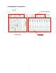
Installation & Connections Audio I/O Control and Tally signal Output interface Input interface 7
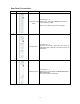
Rear Panel Connections: Item 1 Image Part name Analog Video Input Card Function Description For Input slot 1~ 8.
4 SDI Input Card (With Audio Deembedded output) For Input slot 1~ 8 SDI Video input with de-embedded Audio output thru Mini XLR connector CV encode output for monitoring 5 CHROMA Key Card For slot 9 Dual Channel Chroma Key card Preview Output Card For slot 11 Preview Output card, supports: -. Multi-Image Preview output YUV or CV x 1 -. PGM output YUV x 1 or CV x 2 -.
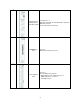
7 SDI CG Overlay Card For slot 12 CG Overlay card, supports: - SDI CG Overlay input x 1 (From PC) - SDI CG Overlay Output x 1 (To PC) - SDI CG Output x 2 SDI PGM Output Card For slot 13 SDI PGM Outputs, support: SDI PGM Output x 2 Gen-Lock BB output x 1 8 9 PGM Output Card For Slot 14 Supports: Y/C (S-Video) Output x 1 YUV output x 1 CV output x 1 DV output x 1 10
10 Remote Cont rol Card For slot 15 Supports: GPI input x 1 RS-232 interface x 1 RS-422 interface x 1 11 Audio Input Audio Input interface, supports: Unbalance Audio input RCA x 2 Balance audio input XLR x 2 12 Audio Output Audio Output interface, supports: Unbalance Audio output RCA x 2 Balance audio output XLR x 2 11
Control Panel Function and Transition Effect Joystick Menu and Control GPI control PRESET and SPD Main/Sub Source T-BAR 12
Control Panel: Item Image Part name Function Description 1 LCD Display LCD Display for SE-900 system configuration and setting 2 Menu and control button SE-900 Functions configuration and setting 3 T-BAR Take bar for manual effects transition 4 Joystick Adjust windows position for PIP For RGB color correction 5 GPI Control and Take-Key Use GPI to trigger the function effect in sequence Take-key for Auto-take the effect by preset speed 6 Video Source Button (Main/ SUB) Selection of Main
Install video interface card 1. Video Input card: 1-1.
2. Install a video output card 2-1 There are certain slot for certain function of video output cards, See the printing from rear panel to install video output cards accordingly. 2-2 Power on SE-900 and check from PGM、PVW output to ensure the installation is correct.
System configuration Press on the “SETTING” button for system configuration, turn the ADJUST Knob to select an item and press down on the Knob to confirm the setting. LCD Menu and Setting 1. CHROMA-KEY Supports Green-Key, Blue-Key and Luma-key Press on the “ADJUST” button to pop up the menu as shown below, turn the “ADJUST” button and select item 1 for Chroma-Key setting. There are two pages of parameters (items 1-19) for Chroma Key setting 1 2 3 4 5 6 7 8 9 10 11 CHROMA KEY NO.
- BKG. Source: Select the Background video input Same as above foreground video setting, CH5-8 is recommended as background video input.
– 99〜 99, Smaller number has less saturation, bigger number has more saturation - Pre. Page: Back to Previous page - ESCAPE: Back to Main menu. *. Some special features on Luma Key adjustment - Dark Level:Adjust the black background level - Dark Grad:Adjust density of black background and level of black transparency and soft edge.
Video input source calibration: 3.1.1- BRIGHTNESS adjustment: default at 0 adjustment range from - 99 to + 99 3.1.2- CONTRAST: default at 0 adjustment range from - 99 to + 99 3.1.3- SATURATIO: default at 0 adjustment range from - 99 to + 99 3.1.4- GBR CORRECTION: GBR correction by system Joystick as below: Press on this button to enable GBR correction 3.1.5- AGC: Automatic Gain Control 3.1.6- 0/7.5 IRE: For NTSC video blanking setup 3.1.7- ALIAS: Assign name for input Camera, such as CAM1… 3.
5. CG INPUT: Works with Datavideo CG-100 with Blackmagic Decklink PCI cards (Decklink 2, Decklink Pro, Decklink SP and Decklink Extreme…) for SDI CG overlay function. CG CARD SETTING 1 MODE EXTERNAL/INTERNAL 2 KEY LEVEL MAX (INTERNAL) 0~255 3 KEY LEVEL MIN (INTERNAL) 0~255 4 5 DARK GRAD (INTERNAL) VER. OFFSET OF SDI_IN ESCAPE 0~100 0~32 6. AUDIO DELAY: -. Adjust audio delay time by frame or mini-second -. From 0 ~ 17 frames or -. From 10 ms to 680 ms -.
7. MULTI. IMAGE: LCD Menu and Setting -. Supports Multi-Image output from CV or YUV -. Top/Bottom image position -. Adjustable screen size 100%, 90% or 80% -. Noise filter MULTI. IMAGE SETTING 1 OUTPUT TYPE 2 IMAGE POSITION 3 SCREEN SIZE 4 NOISE FILTER 5 ESCAPE YUV, CV, TOP, BOTTOM 100% ,90% ,80% BYPASS, LOW, MID, HIGH 1 2 3 4 5 6 7 8 9 10 11 12 CHROMA KEY VIDEO IN VIDEO OUT LOGO (LUMA KEY) CG INPUT AUDIO DELAY MULTI. IMAGE EXT. GENLOCK SYSTEM CONTROLLER STORE & RECALL UPDATE FIRMWARE ESCAPE 8. EXT.
LCD Menu and Setting 10. CONTROLLER: -. LCD contras and backlight level control -. RS-232 Remote mode setting -. Switch light setting CONTROLLER SETTING 1 LCD CONTRAST 2 LCD BACK LIGHT 3 REMOTE MODE 4 SWITCH COLOR 5 SWITCH BRIGHTNESS ESCAPE 1~ 8 LEVEL 1~ 8 LEVEL RS-232 SWAP, NO SWAP 1~ 4 LEVEL 1 2 CHROMA KEY VIDEO IN 3 4 5 6 VIDEO OUT LOGO (LUMA KEY) CG INPUT AUDIO DELAY 7 8 9 10 MULTI. IMAGE EXT. GENLOCK SYSTEM CONTROLLER 11 12 STORE & RECALL UPDATE FIRMWARE ESCAPE LCD Menu and Setting 11.
CONTROL PANEL OPERATION PIP, Mosaic and Paint effect Chroma-key, CK w/sync and CG Strobe, B/W effect and LOGO Border, Border color and Background color PIP (Picture in Picture): To enable the PIP preview function on SE-900 -. Set the PIP windows for output video -. Press on PIP button to preview output on the windows -.
Setup example of Multi-Camera CHROMA-KEY operation in SYNC: Equipments for Multi- Camera Chroma-Key Setup -. 2 or more camera for FG source inputs -. 2 or more BG video source inputs Connection: FG-2 FG-1 BG-1 Video in 1~ 4 Video in 5~ 8 SE-900 PGM OUT Chroma Sync- 1 Chroma Sync- 2 Operating procedure: 1. 2. 3. 4.
CG (SDI CG OVERLAY) - Connecting SDI Overlay In/Out from SE-900 to PC Decklink card SDI Out/In. - Press on “CG” button to enable CG overlay - Enable CG-100 software and run a VCG file -.
Others Effect Keys BG (Background) - Press on “BG” button on the video sub-source line - Push on T-Bar to switch PGM to background color output FTB (FADE TO BLACK) - Press on “FTB” button - Press on T-Bar to fade out to black FZ (Freeze) - Press on “FX” button to freeze PGM output - Press again to release Speed Key Setting (Effect transition speed) (Not available yet) -. Transition Speed setting - Select from LCD MENU - SPEED SETTING 1~ 5 -. Enable / Disable transition speed - Press on “SPD” button -.
Transition Effects: 1 9 Left High to Right Down Left to Right 2 10 Right Down to Left High Right to Left 3 11 Left Down to Right High Bottom UP 4 12 Top to Bottom 5 Right High to Left Down 13 Middle extend U/D 6 Outside In 14 Inside Out Squeeze 7 15 Middle extend U/D Fade IN/OUT 8 Middle extend L/R Remote Control Interface -. RS-232 Remote: Proprietary Datavideo Protocols -. RS-422 Remote: Sony Protocol -.
SPECIFICATION Digital Video Input: SDI(SMPTE 272M-C 270Mbps with Embedded Audio) 8-CH Video inputs Video Outputs DV25, (25Mbps, Y.U.V. 4:1:1 NTSC or Y.U.V. 4:2:0 PAL) Analog Video Input: Y/C 和 Composite compliant to CCIR601 NTSC & PAL Component Y.U.V Sony Betaca m Spec VGA (Not available yet) DV, YUV, Y/C & Composite, Optional SDI output Bandwidth: > 5.
Service and Support It is our goal to make your products ownership a satisfying experience. Our supporting staff is available to assist you in setting up and operating your system. Please refer to our web site www.datavideo-tek.com for answers to common questions, support requests or contact your local office below. Datavideo Corporation (USA) 12300-U East Washington Blvd., Whittier, CA 90606 USA Tel: +1 562 696 2324 contactus@datavideo.us www.datavideo.