Instruction Manual NOR-RAY-VAC CONTINUOUS RADIANT TUBE SYSTEM INSTALLATION INSTRUCTION INDEX MANUAL Section Installation Requirements ------------------------------------------------ 1 User and Operating Instructions ---------------------------------------- 2 WARNINGS AmbiRad equipment must be installed and maintained in accordance with the relevant provisions of the Gas Safety (Installations and Use) Regulations 1998 for gas fired products.
Document Index. 1 Installation Requirements 1.1 Health & Safety 1.2 Burner Model Definitions 1.3 Heater Suspension 1.4 Clearance to Combustibles 1.5 Gas Connection & Supply Details 1.6 Electrical Connections 1.6.1 Typical Wiring Schematic 1.6.2 Wiring Details 1.7 Ventilation Requirements 1.8 Exhaust & Air Inlet Options 1.8.1 Exhaust Flue Considerations 1.8.2 Ducted Air Inlet Considerations 1.9 Vacuum Fan Details 1.10 Technical Data 2 User and Operating Instructions 2.1 To Start Heater 2.
Introduction. Welcome to the range of Nor-Ray-Vac ‘LR’ series continuous radiant tube heaters. The Nor-Ray-Vac ‘LR’ series system complies with the requirements of the European Gas Appliance Directive BS EN777-4. Local regulations may vary in the country of use and it is the installers responsibility to ensure that such regulations are satisfied. number of radiant branches manifolded together, linked by a tail pipe to a vacuum fan discharging the spent products of combustion to atmosphere.
1.3 1.3.2.3 A support must always be located at a maximum distance of 2m from a tee or elbow fitting. Heater Suspension 1.3.1 First considerations • • • • 1.3.2.4 Except for the combustion chamber support lug suspension points, suspension support brackets are installed to support the tube section which is then covered with reflectors. Clearances from combustibles must be maintained.
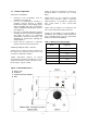
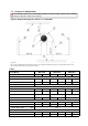
Figure 1.b Clearance for servicing - distances to walls and obstacles above. G Figure 1.c Clearance for servicing - distances to obstacles above.
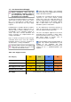
1.4 Clearance to Combustibles. The minimum clearances to combustible materials are given in table 2 below. These minimum distances MUST be adhered to at all times.
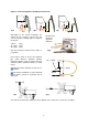
1.5 Gas Connection and Supply Take care when making a gas connection to the heater not to apply excessive turning force to the internal controls. Before installation, check that the local distribution conditions, nature of gas and pressure, and adjustment of the appliance are compatible. A flexible hose is installed to allow safe linear expansion to each burner without creating undue stress on the gas supply pipe work.
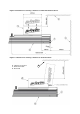
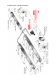
Figure 3. Correct Installation of Flexible Gas Connection x fig.b fig.a Depending on the specific installation, the flexible gas hose may be routed to the gas cock at any of the following angles in relation to the burner: Vertical 45° angle 90° angle fig.c x Arrow denotes direction of expansion. (fig.a) (fig.b) (fig.c) fig.d Any other position in between these angles is acceptable.
1.6 Electrical Connections should be of 0.5mm² minimum and comply with BS 6500. For fan and LRU supply, the wire size must be suitable for the current ratings as listed in Table 10. Standard burner 16W. Current rating 0.05 amp per burner Fuse: external 3 amp. Each component carrying an electrical supply must be earthed. Supply for burners is 230V 50Hz single phase. * Exhaust fans are three phase 415V 50Hz.
In-line Burner To ‘Mains In’ on End Vent Burner 230V 50Hz 13A Mains Supply End Vent Module SmartCom³ no.1 ‘Master’ (SC3-MZ) Isolator 0.75mm² Screened Cable Sensor Zone 1 Isolator Networking Cable Screened pair Beldon 9841 or equiv * 4 core Armoured Cable End Vent Burner 0.75mm² Screened Cable * IMPORTANT For Inverter Panels only (fan types B80/B160 & B300) MAXIMUM length of cable between Inverter and Fan is 5m. Sensor Zone 2 Fused Spur End Vent Module SmartCom³ no.
1.6.2 Wiring Details Figure 4.c. LR internal wiring diagram - End Vent Burner (EV) MAINS INPUT IGNITOR GRN/YEL 8 12 3 7 11 2 10 1 9 MAIN J.S.T. RED MAINS ON 4 DELAY TIMER BURNER ON BLACK BLUE 2 BROWN LAMPS BLACK GREY 3 BLUE BLUE BLUE GREEN/YELLOW BROWN N FLAME SENSOR RED EMC FILTER SOLENOID VALVE PURPLE L 1 5 4 3 2 1 VALVE J.S.T. RED BLUE POWER OUT BLUE N GREEN/YELLOW VACUUM SWITCH RED N.O. L C. N.C. Figure 4.d.
Figure 4.e. LR internal wiring diagram - End Vent Burner c/w N/O or N/C volt free Lockout contacts EMC FILTER IGNITOR PURPLE L3 GRN/YEL BROWN RELAY N.C. A1 Detail shows either N.O. or N.O. contacts A2 3 SOLENOID VALVE LAMPS BLUE 2 BLUE BLUE MAINS ON 4 8 12 3 7 11 2 10 1 9 MAIN J.S.T. RED C. BLUE L1 GREEN/YELLOW N.O. BROWN L2 BLACK DELAY TIMER BURNER ON BLACK N FLAME SENSOR GREY MAINS INPUT 1 VALVE J.S.T.
Figure 4.g. LR internal wiring diagram - End Vent Burner c/w 3 way solenoid valve MAINS INPUT IGNITOR PURPLE LAMPS MAINS ON BLUE 2 4 8 12 3 7 11 2 10 1 9 MAIN J.S.T. DELAY TIMER BURNER ON BLACK 3 SOLENOID VALVE BROWN BLUE RED 1 BLUE BLUE BLUE 2 GREEN/YELLOW 3 WAY AR SOLENOID BLACK GREY BROWN N FLAME SENSOR RED GRN/YEL EMC FILTER RED L 1 5 4 3 2 1 VALVE J.S.T. RED BLUE POWER OUT BLUE N GRN/YEL VACUUM SWITCH RED L N.O. C. N.C. RED Figure 4.h.
Figure 4.j. NRV Inverter Internal Wiring Diagram for B80, B160 and B300 three phase fans E L R/L1 15V 0V AI1 RC Fan Trip Circuit t3 tW tV TO FAN tU FAN HEALTHY LAMP t4 Brown VF Enable Circuit t2 W/T3 V/T2 U/T1 Brown t1 Brown N LI1 Violet 3Ph Supply To Fan S/L2 V.S.D.1 Orange 230V 50Hz 1 Ph Supply L Blue Brown Green/Yellow MAINS ON LAMP RA E N 230V 50HZ 1 Pha SUPPLY A1 11 A2 12 1 2 3 4 E E L L N N U V W TERMINAL RAIL Figure 4.k.
4-Core Armoured or Screened Cable 1.5mm² MPORTANT For Inverter panels only (fan types B80 / B160 & B300): MAXIMUM length of cable between inverter and fan is 5m (EMC class A building) or 10m (EMC class B building). N.B. if in doubt, do not exceed 5m. 230V 1P 22A 230V 1P 22A 230V 1P 30A B80 B160 B300 THE LOCAL RELAY UNIT houses an inverter. This converts the 230V single-phase input into a three-phase 230V output.
415V 3P 25A BH300 FAN MOTOR 415V 3-Phase Supply. Motor must be wired DELTA L3 L2 L1 L1 N 4-Core Armoured Cable THE LOCAL RELAY UNIT houses a 3pha motor contactor and overload plus any additional fan logic circuitry.
*The power supply is non-isolated, 4-Core Armoured or Screened Cable 1.5mm² 230V 1P 22A 230V 1P 22A 230V 1P 30A B80 B160 B300 THE LOCAL RELAY UNIT houses an inverter. This converts the 230V single-phase input into a three-phase 230V output. The inverter provides a soft start to the motor, which extends the motor life by minimising the start current.
*The power supply is non-isolated, 4-Core Armoured or Screened Cable 1.5mm² 230V 1P 22A 230V 1P 22A 230V 1P 30A B80 B160 B300 THE LOCAL RELAY UNIT houses an inverter. This converts the 230V single-phase input into a three-phase 230V output. The inverter provides a soft start to the motor, which extends the motor life by minimising the start current.
1.8.2 Vertical discharge 1.7 Ventilation Requirements Nor-Ray-Vac heaters are installed as flued appliances in accordance with the relevant national requirements in the country of installation. In buildings having an air change rate of less than 0.5 per hour, additional ventilation is required. For detailed information, please see BS6896 section 5.2.2.2.1 Natural Ventilation Low level ventilation openings with a free area of at least 2cm²/kW shall be provided. See BS6896 section 5.2.2.2.2.1. 1.
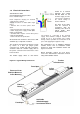
1.8.3 Ducted Air Inlet Considerations. Ensure that the flexible ductwork is installed to allow for expansion of the heating system. Heat resistant flexible tube is connected to the burner assembly ducted air adaptor and the EVM ducted air adaptor and connected to the air supply duct On a header duct, the main air supply header which is feeding the individual branch ducts and burner/end vent supply ducts must have a maximum pressure drop of 0.25 mbar (0.1in wg).
1.
1.10 Technical Details. Tables 4a & b Burner Details No of Injectors 1 Gas Connection ½ in BSP Internal thread Burner current 0.05 (per burner) Electrical Voltage/Ph/Hz 230 volt 1 phase 50Hz Burner Type 12LR 18LR 24LR 32LR 38LR 46LR Burner Details Gas Category II G20 Natural Gas Heat input (Gross) kW 12 18 24 32 38 46 Gas consum rate Nat Gas G20 m³/h 1.14 1.72 2.29 3.05 3.62 4.38 Max Inlet pressure Nat Gas G20 mbar 50 Min Inlet Pressure Nat Gas G20 mbar 17.
Tables 4c & d Burner Details Burner Type 12LR 18LR 24LR 32LR 38LR 46LR Burner Details Gas Category III G30 Butane Gas Heat input (Gross) kW 12 18 24 32 38 46 Gas consum rate Butane G30 m³/h 0.34 0.52 0.69 0.92 1.09 1.32 Max Inlet pressure Butane G30 mbar 35 Min Inlet Pressure Butane G30 mbar 20 Hs Butane G30 MJ/m³ 125.81 Hi Butane G30 MJ/m³ 116.09 d Butane G30 2.075 Ws Butane G30 MJ/m³ 87.33 Wi Butane G30 MJ/m³ 80.
Table 5. Heater Details Burner Type 12LR 18LR 24LR 32LR 38LR 46LR Min distance between burners m 5.2 7.4 9.4 14 18 23 Max distance between burners m 7.2 10.2 13.1 18 23 27 Min distance between burner and fitting m 3.6 3.6 5.0 6.0 7.0 8.0 Max tube temp °C Min mounting height m 450 480 3.0 3.6 4.0 4.7 5.3 6.
Table 9. Fan Details Fan Size B80 B160 B300 BH300 201760 201761 201762 201763 QS 80M2B H QS 90S2A-40H QS 90L2A H QS 112M2A H kW 1.1 1.5 2.2 4.0 V/Hz/P 230~50/3 230~50/3 230~50/3 400~50/3 Run Current A 4.38 5.6 8.48 7.2 Start Current A n/a n/a n/a 54.0 RPM 2850 2860 2840 2880 Inverter ∆ ∆ ∆ Fan part number Motor (TEE) Power Supply to Fan Speed Wired D.O.L.
Notes.
Notes.
2. User & Operating Instructions. To Start the Heater 2.3 1. Ensure that gas supply is turned on at each burner. After ensuring that the heater is cold and mains electric isolated, cleaning of the reflectors with a soft cloth and a mild detergent (non solvent based cleaners only) in water can be undertaken. 2. Switch on electrical supply to heaters. 3. Ensure that the controls are correctly set i.e.