Before using the LCD projector, please read this operation manual carefully. Important ENGLISH Information OPERATION MANUAL ENGLISH IMPORTANT For your assistance in reporting the loss or theft of your Color LCD Projector, please record the Serial Number located on the bottom of the projector and retain this information. Before recycling the packaging, please be sure that you have checked the contents of the carton thoroughly against the list of “Supplied Accessories” on page 10. Model No.
INFORMATION Important • • • • ENGLISH Information This equipment has been tested and found to comply with the limits for a Class B digital device, pursuant to Part 15 of the FCC Rules. These limits are designed to provide reasonable protection against harmful interference in a residential installation. This equipment generates, uses, and can radiate radio frequency energy and, if not installed and used in accordance with the operation manual, may cause harmful interference to radio communications.
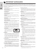
IMPORTANT SAFEGUARDS Important Information Electrical energy can perform many useful functions. This product has been engineered and manufactured to ensure your personal safety. However IMPROPER USE CAN RESULT IN POTENTIAL ELECTRICAL SHOCK OR FIRE HAZARD. In order not to defeat the safeguards incorporated into this LCD Projector, observe the following basic rules for its installation, use and servicing.
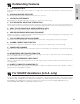
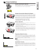
Outstanding Features Important Information 1. FOR USE WITH DTV Allows projection of DTV images and 16:9 wide-screen images when connected to a DTV decoder or similar video systems. (Page 11) 2. ADVANCED VIDEO CIRCUITRY Provides high quality images with minimal dot crawl and cross color noise. 3. 3D DIGITAL UNIFORMITY Equipped with new 3D digital uniformity technology for a clearer, more uniform image. 4.
Contents Important Information Important Information Setup & Connections IMPORTANT SAFEGUARDS …………………… Outstanding Features …………………………… For SHARP Assistance (U.S.A.
Usage Guidelines Important Information Caution Concerning the Lamp Unit Potential hazard of glass particles if lamp ruptures. Please have the nearest Authorized SharpVision Service Center or Dealer replace lamp if rupture occurs. See “Replacing the Projection Lamp” on pages 38 and 39.
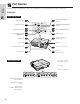
Part Names Important Information Numbers next to the part names refer to the main pages in this manual where the topic is explained. Projector Front and Top View ON/OFF button 15 POWER indicator 15 ON/OFF 37 LAMP REPLACEMENT indicator 37 TEMPERATURE WARNING indicator 31 20 PICT MODE/ENTER button LAMP POWER TEMP.
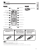
Part Names Front View Important Information Remote Control Top View VOLUME buttons 16 MUTE button 16 VOL Mouse (∂/ƒ)/ Adjustment (∂/ƒ) buttons 20 MUTE RGB/COMPONENT button 12 INPUT 1 button 16 POWER BACK 15 POWER button 20 BACK button 20 MENU button 20 ENTER button 26 AUTO SYNC button 31 PICT MODE button Remote control signal transmitter MENU ENTER RGB/ INPUT 1 COMPONENT PICT MODE INPUT 2 AUTO SYNC GAMMA INPUT 2 button 16 S-VIDEO VIDEO CLR TEMP KEYSTONE FREEZE S-VID
Part Names Important Information Attaching the Rubber Leg Tips The rubber leg tips are provided to prevent the remote control from skidding and shaking over a flat surface. Positioning the Remote Control The remote control can be used to control the projector within the ranges shown below. • The signal from the remote control can be reflected off a screen for easy operation. However, the effective distance of the signal may differ due to the screen material.
Setup & Connections Supplied Accessories Setup & Connections Rubber leg tips for remote control GLEGG9095CEZZ E-10
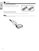
Connecting the Projector Connecting the Power Cord Plug the supplied power cord into the AC socket on the back of the projector. Setup & Connections Power cord CACCU5013DE01 Connecting the Projector to Audiovisual Equipment You can connect your projector to a VCR, laser disc player, DVD player, DTV decoder and other audiovisual equipment. CAUTION • Always turn off the projector while connecting to audiovisual equipment, in order to protect both the projector and the equipment being connected.
Connecting the Projector Connecting an audiovisual source (DTV decoder or DVD player) using the RCA input Setup & Connections 1 Connect each RCA connector to the corresponding INPUT 1/COMPONENT terminals on the projector. 2 Connect the other end of the cable to the corresponding terminals of a DVD player or DTV decoder. 3 To use the built-in audio system, connect one end of an audio cable to the AUDIO INPUT (INPUT 1, 2) terminal on the projector.
Setup & Connections Connecting the Projector E-13
Connecting the Projector Connecting RS-232C Port When the RS-232C port on the projector is connected to a computer with an RS-232C cable (null modem, cross type, sold separately), the computer can be used to control the projector and check the status of the projector. See pages 43 and 44 for details. DIN-D-sub RS-232C cable QCNW-5288CEZZ Setup & Connections 1 Connect the supplied DIN-D-sub RS-232C cable to the RS-232C port on the projector.
Operation Basic Operations 1 Make the necessary connections before proceeding. Connect the power cord to a wall outlet. The POWER indicator illuminates red and the projector enters standby mode. Maintenance indicators ON/OFF POWER LAMP • If the side filter cover is not securely installed, the POWER indicator flashes. TEMP. KEYSTONE Operation Projector ON/OFF Remote control VOL LAMP POWER POWER 2 TEMP.
Basic Operations Projector ON/OFF Remote control LAMP POWER TEMP. 5 Press INPUT on the projector, INPUT 1, INPUT 2, S-VIDEO or VIDEO on the remote control to select the desired input mode. Press INPUT, INPUT 1, INPUT 2, S-VIDEO or VIDEO again to change the mode. KEYSTONE INPUT PICT MODE BACK ENTER • When the selected input signal is being received, “Adjusting The Image” will be displayed. • When no signal is being received, “NO SIGNAL” will be displayed.
Setting up the Screen Position the projector perpendicular to the screen with all feet flat and level to achieve an optimal image. Move the projector forward or backward if the edges of the image are distorted. • The projector lens should be centered in the middle of the screen. If the lens center is not perpendicular to the screen, the image will be distorted, making viewing difficult. • Position the screen so that it is not in direct sunlight or room light.
Setting up the Screen Using the Adjustment Feet You can adjust the height of the image by raising the projector with the foot releases. 1 Press the foot releases and lift the projector to the desired angle. (Adjustable up to approximately 7° from the standard position.) 2 Remove your hands from the foot releases. Once the adjustment feet have locked in position, release the projector. 3 If the screen is at an angle, the adjusters can be used to adjust the angle of the image.
Setting up the Screen Digital Keystone Correction • When the image is distorted due to the projection angle, the digital keystone correction function allows you to correct it. • The digital keystone correction can be made by pressing KEYSTONE, or by setting “Keystone” correction in the GUI menu. Projector ON/OFF Remote control RGB/ INPUT 1 COMPONENT PICT MODE LAMP POWER TEMP.
Using the GUI (Graphical User Interface) Menu Screens Projector 7 ON/OFF VOL LAMP POWER This projector has three sets of menu screens (INPUT 1 or 2 (COMPONENT), INPUT 2 (RGB) and S-VIDEO or VIDEO) that allow you to adjust the image and various projector settings. These menu screens can be operated from the projector or the remote control with the following buttons. Remote control POWER 2, 4, 6 TEMP.
Using the GUI (Graphical User Interface) Menu Screens Items on the INPUT 1 or 2 (COMPONENT) Mode Menu Bar Main menu Picture1 Sub menu Main menu Contrast ⳮ30 Ⳮ30 Bright ⳮ30 Red Blue Operation Ⳮ30 Bright ⳮ30 Ⳮ30 ⳮ30 Ⳮ30 Red ⳮ30 Ⳮ30 ⳮ30 Ⳮ30 Blue ⳮ30 Ⳮ30 Component Signal Type RGB Reset RGB Color ⳮ30 Ⳮ30 Clock ⳮ127 Ⳮ127 Tint ⳮ30 Ⳮ30 Phase ⳮ120 Ⳮ120 Fine Sync H-Pos ⳮ50 Ⳮ50 2D Progressive V-Pos ⳮ50 Ⳮ50 Reset 3D Progressive Reset Signal Info Film Mode 1 Signal Inf
Using the GUI (Graphical User Interface) Menu Screens Items on the S-VIDEO or VIDEO Mode Menu Bar Main menu Picture1 Sub menu Contrast ⳮ30 Ⳮ30 Bright ⳮ30 Ⳮ30 Red ⳮ30 Ⳮ30 Blue ⳮ30 Ⳮ30 ⳮ30 Ⳮ30 Reset Picture2 Color Tint Options ⳮ30 Ⳮ30 Sharp 0 7 Progressive 2D Progressive Reset 3D Progressive Signal Info Film Mode 1 Lamp Timer Film Mode 2 Keystone ⳮ127 Ⳮ127 Auto Power Off ON Background OFF Theater Mode Blue English None Deutsch ON Español OFF Operation Language *3
Selecting the On-screen Display Language Remote control Projector ON/OFF VOL LAMP POWER POWER 2, 3 English is the preset language for the On-screen Display. The language can be set to English, German, Spanish, Dutch, French, Italian, Swedish, Portuguese, Chinese, Korean or Japanese. TEMP. KEYSTONE INPUT 2, 4 PICT MODE BACK ENTER MUTE 1 Press MENU. BACK MENU 2 Press ∂/ƒ to select “Language”, and then press ENTER. MENU 1, 5 ENTER 3 Press ∂/ƒ to select the desired language.
Picture Adjustments Projector ON/OFF Remote control VOL LAMP POWER POWER 2, 3, 4 TEMP. PICT MODE BACK ENTER You can adjust the projector’s picture to your preferences with the following picture settings.
Picture Adjustments Projector ON/OFF Remote Control VOL LAMP POWER POWER 2, 3, 4 TEMP. PICT MODE BACK ENTER This function allows you to select the input signal type (RGB or COMPONENT) for INPUT 2 port. 1 Press MENU. KEYSTONE INPUT Selecting the Signal Type 2, 3, 5 MUTE BACK MENU MENU 1, 6 2 Press ∂/ƒ to select “Picture” in INPUT 2 (RGB) mode, and then press ENTER. ENTER 3 Press ∂/ƒ to select “Signal Type”, and then press ENTER.
Computer Image Adjustments (INPUT 2 (RGB) mode only) Auto Sync Adjustment Remote control • Used to automatically adjust a computer image. • Auto Sync adjustment can be made manually by pressing AUTO SYNC. RGB/ INPUT 1 COMPONENT PICT MODE INPUT 2 AUTO SYNC GAMMA 1 S-VIDEO VIDEO CLR TEMP KEYSTONE FREEZE • The sync adjustment is automatically made each time the projector is turned on while connected to a computer or the input selection is changed. 1 Press AUTO SYNC on the remote control.
Computer Image Adjustments (INPUT 2 (RGB) mode only) Projector ON/OFF Remote control VOL LAMP POWER POWER 2, 3, 4 TEMP. KEYSTONE INPUT PICT MODE BACK ENTER 2, 3 MUTE BACK MENU Adjusting the Computer Image When displaying computer patterns which are very detailed (tiling, vertical stripes, etc.), interference may occur between the LCD pixels, causing flickering, vertical stripes, or contrast irregularities in portions of the screen.
Useful Features Freeze Function Remote control This function allows you to instantly freeze a moving image. This is useful when you want to display a still image from a computer or video, giving you more time to explain the image to the audience. 1 Press FREEZE on the remote control to freeze the image. 2 Press FREEZE again to return to the moving image.
Adjusting the Color Temperature Remote control This function can be used to adjust the color temperature to suit the type of image input to the projector (video, computer image, TV broadcast, etc.). Decrease the color temperature to create warmer, reddish images for natural flesh tones. Increase the color temperature to create cooler, bluish images for a brighter picture. Description of Color Temperature 1 (Red) 2 Decreases color temperature for warmer, reddish, incandescent-like images.
Gamma Correction Remote control RGB/ INPUT 1 COMPONENT PICT MODE INPUT 2 AUTO SYNC GAMMA 1 S-VIDEO VIDEO CLR TEMP KEYSTONE FREEZE • Gamma is an image quality enhancement function that offers a richer image by brightening the darker portions of the image without altering the brightness of the brighter portions. • Three gamma settings are available to allow for differences in the images displayed and in the brightness of the room.
Selecting the Picture Display Mode Remote control ON/OFF LAMP POWER This function allows you to modify or customize the picture display mode to enhance the input image. Depending on the input signal, you can choose the picture display mode preferred. TEMP. KEYSTONE INPUT PICT MODE BACK ENTER MENU Useful Features EXAMPLE E-31 1 Press PICT MODE. Each time PICT MODE is pressed, the picture mode changes as shown below.
Checking the Input Signal and the Lamp Usage Time Projector ON/OFF Remote control VOL LAMP POWER POWER 2 This function allows you to check the current input signal information and the accumulated lamp usage time. 1 Press MENU. TEMP. KEYSTONE INPUT 2 PICT MODE BACK ENTER MUTE BACK MENU MENU 1 2 Press ∂/ƒ to select “Options”, and then press ENTER. The current input signal information and the lamp usage time will be displayed.
Selecting a Background Image Projector ON/OFF Remote control VOL LAMP POWER POWER 2, 3, 4 This function allows you to select the image displayed when no signal is being sent to the projector. Description of Background Images TEMP. KEYSTONE INPUT PICT MODE BACK ENTER 2, 3 MUTE BACK MENU Blue Blue screen None Black screen *1 MENU 1, 5 1 Press MENU. ENTER 2 Press ∂/ƒ to select “Options”, and then press ENTER.
Reverse/Invert Image Function Projector Remote control This projector is equipped with a reverse/invert image function which allows you to reverse or invert the projected image for various applications. Description of Projected Images (GUI) On-screen Display Selected item Projected image Front Normal image CeilingⳭFront Inverted image Rear Reversed image CeilingⳭRear Reversed and inverted image 1 Press MENU. 2 Press ∂/ƒ to select “PRJ Mode”, and then press ENTER.
Air Filter Maintenance Maintenance & Troubleshooting Air Filter Maintenance Right Side View Air filter • This projector is equipped with an air filter to ensure the optimal operating condition of the projector. • The air filter should be cleaned every 100 hours of use. Clean the filters more often when the projector is used in a dusty or smoky location. • Have your nearest Authorized SharpVision Service Center or Dealer exchange the filter (PFILD0123CEZZ) when it is no longer possible to clean it.
Air Filter Maintenance Replacing the air filter 1 Disconnect the power cord. Unplug the power cord from the AC socket. 2 Remove the filter cover. Turn over the projector. Press the tab and remove the filter cover in the direction of the arrow. 3 Remove the air filter. 1 Remove the air filter stopper. 2 Remove the air filter.
Lamp/Maintenance Indicators Maintenance Indicators ON/OFF POWER POWER indicator LAMP LAMP REPLACEMENT indicator TEMP. KEYSTONE Maintenance Indicator TEMPERATURE WARNING indicator LAMP REPLACEMENT indicator POWER indicator TEMPERATURE WARNING indicator Condition The internal temperature is abnormally high. • The warning lights on the projector indicate problems inside the projector.
Replacing the Projection Lamp CAUTION: • Potential hazard of glass particles if lamp ruptures. Please have the nearest Authorized SharpVision Service Center or Dealer replace lamp if rupture occurs. • Do not remove the lamp cage directly after operation of the projector. The lamp may be extremely hot. Wait at least one hour after the power cord is disconnected to allow the surface of the lamp cage to fully cool before removing the lamp cage.
Replacing the Projection Lamp 7 Remove the lamp cage cover. Turn over the projector and loosen the user service screw that secures the lamp cage cover. Then lift open the cover in the direction of the arrow. 9 8 Remove the lamp cage. Loosen the securing screws on the lamp cage. Hold the lamp cage by the handle and pull it towards you. 10 Insert the new lamp cage. Press the lamp cage firmly into the lamp cage compartment. Fasten the securing screws. Attach the lamp cage cover.
Using the Kensington Lock This projector has a Kensington Security Standard connector for use with a Kensington MicroSaver Security System. Refer to the information that came with the system for instructions on how to use it to secure the projector.
Appendix Attaching the Lens Cap Put on the lens cap to prevent damage to the lens when transporting the projector. A lens cap strap is provided to prevent the loss of the lens cap. 1 Attach the lens cap strap to the lens cap. 2 Attach the lens cap strap to the projector. 3 Attach the lens cap to the projector with the lens cap eyelet facing up. CAUTION • Do not lift or carry the projector by the lens or the lens cap as this may damage the lens.
Connection Pin Assignments INPUT 2 Port: 15-pin mini D-sub female connector 1 6 11 5 10 15 Computer Input Analog 1. Video input (red) 2. Video input (green/sync on green) 3. Video input (blue) 4. Not connected 5. Composite sync 6. GND (red) 7. GND (green/sync on green) 8. GND (blue) 9. 10. 11. 12. 13. 14. 15. Not connected Not connected GND Bi-directional data Horizontal sync signal Vertical sync signal Data clock RS-232C Port: 9-pin D-sub male connector of the DIN-D-sub RS-232C cable Pin No.
RS-232C Port Specifications PC control A computer can be used to control the projector by connecting an RS-232C cable (null modem, cross type, sold separately) to the projector. (See page 14 for connection.) Communication conditions Set the serial port settings of the computer to match that of the table. Signal format: Conforms to RS-232C standard.
RS-232C Port Specifications Commands EXAMPLE • When “BRIGHT” of RGB IMAGE ADJUSTMENT is set to 10.
Computer Compatibility Chart Horizontal Frequency: 15–80 kHz Vertical Frequency: 43–85 Hz Pixel Clock: 12–108 MHz Compatible with sync on green and composite sync signals SXGA (1,280 1,024) compatible in intelligent compression PC/ MAC/ WS Resolution 640 350 720 350 640 400 VGA 720 400 PC 640 480 SVGA XGA 800 600 1,024 768 Horizontal Frequency (kHz) Vertical Frequency (Hz) VESA Standard Display PC/ MAC/ WS Resolution 27.0 60 31.5 70 37.9 85 27.0 60 31.5 70 27.
Specifications Product type Model Video system Display method LCD panel Lens Projection lamp Contrast ratio Video input signal S-video input signal Component input signal Horizontal resolution Audio output Computer RGB input signal Pixel clock Vertical frequency Horizontal frequency Computer control signal Speaker system Rated voltage Input current Rated frequency Power consumption Operating temperature Storage temperature Cabinet I/R carrier frequency Dimensions (approx.) Weight (approx.
INPUT 1 Y /COMPONENT CB CR AUDIO INPUT (INPUT 1, 2) ON/OFF POWER Appendix RS-232C E-47 LAMP TEMP.
Glossary Active digital keystone correction Corrects keystone distortion caused when the projected image is not perpendicular to the screen. This method provides not only horizontal correction, but vertical as well, thus maintaining the original 4:3 aspect ratio and eliminating jag lines. Aspect ratio Width and height ratio of an image. The normal aspect ratio of a computer and video image is 4 : 3. There are also wide images with an aspect ratio of 16 : 9 and 21 : 9.