
User's Manual


.
ObserveImportantWiringInformation
Important:Thisswitchisratedforandintendedtoonlybeusedwithcopperwire.
Thehome’selectricalwiresmaybeattachedtothescrewterminalsorinsertedintotheholesinthe
backoftheswitchenclosureandclampedinplacebytighteningthescrewterminals.
Alwaysfollowthe
recommendedwirestriplengthswhenmakingwiringconnections.
Wiregaugerequirements
•Use14AWGorlargerwiressuitableforatleast80°Cforsupply(HOT),Load,Neutral,Groundand
Travelerconnections.
Wirestriplength:
•Forattachmenttoscrewterminals:Stripinsulation1in(25mm)
•Forattachmentusingtheenclosure’sholes:Stripinsulation5/8”(16mm)
ULspecifiesthatthetighteningtorqueforthescrewsis14Kgf‐cm(12lbf‐in).
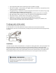
SINGLESWITCHWIRING
1.Shutoffpowertothecircuitatfuseboxorcircuitbreaker.
2.Removewallplate.
!Warning:Verify
powerisOFFtoswitchboxbeforecontinuing.
3.Removetheswitchmountingscrews.
4.Carefullyremovetheswitchfromtheswitchbox.DONOTdisconnectthewires.
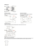
5.Therearefivescrewterminalsontheswitch;thesearemarked
LINE(Hot)
Neutral
LOAD
GROUND
TRAVELER
TheTravelerterminalisonlyusedfor3‐wayor4‐waywiringandshouldremaininsulatediftheswitchis
beinginstalledina2‐waysystem(oneswitch&oneload).Matchthesescrewterminalstothewires
connectedtotheexistingswitch.
6.Disconnectthewiresfrom
theexistingswitch.
7.ConnectthegreenorbarecoppergroundwiretotheGROUNDterminal.
8.ConnecttheblackwirethatgoestothelighttotheterminalmarkedLOAD.
9.Connecttheblackwirethatcomesfromtheelectricalservicepanel(Hot)totheterminalmarked
LINE.
10.Connect
thewhitewiretotheneutral terminal.
Note:ULspecifiesthatthetighteningtorqueforthescrewsis14Kgf‐cm(12lbf‐in).
11.InsertSwitchintotheswitchboxbeingcarefulnottopinchorcrushwires.
12.Securetheswitchtotheboxusingthesuppliedscrews.
13.Mountthewallplate.
14.Reapplypowertothecircuitatfuseboxorcircuitbreakerandtestthesystem.