AIR-JACKETED CO2 INCUBATORS 115 Volts Installation and Operation Manual SCO58 SCO40 SCO31 Previously designated: 2460, 2440, 2428
AIR-JACKETED CO2 INCUBATORS 115 Voltage Installation and Operation Manual Part Number (Manual): 4861710 Revision: December 24, 2014 Pictured on front cover: SCO58 SCO40 SCO31 These units are compliant with the following standards for use within an ambient air pressure range of 22.14 – 31.3 inHg (75 – 106 kPa), with no flammable, volatile, or combustible materials being heated. CAN/CSA C22.2 No. 61010-1:2012 CAN/CSA C22.2 No.
TABLE OF CONTENTS INTRODUCTION........................................................................................................................................... 4 General Safety Considerations ................................................................................................................. 4 Engineering Improvements ....................................................................................................................... 5 Contacting Assistance .........................
INTRODUCTION Thank you for purchasing a Sheldon SCO Series Air-Jacketed CO2 Incubator. We know that in today’s competitive marketplace, customers have many choices when it comes to constant temperature equipment. We appreciate you choosing ours. Our continued reputation as a leading laboratory product manufacturer rests with your satisfaction. Sheldon Manufacturing, Inc. stands behind our products, and we will be here if you need us.
INTRODUCTION (CONTINUED) ENGINEERING IMPROVEMENTS Sheldon Manufacturing continually improves all of its products. As a result, engineering changes and improvements are made from time to time. Therefore, some changes, modifications, and improvements may not be covered in this manual. If your unit’s operating characteristics or appearance differs from those described in this manual, please contact your Shel Lab dealer or distributor for assistance.
RECEIVING YOUR INCUBATOR Before leaving our factory, all SCO Incubators are packaged in high-quality shipping materials to provide protection from transportation-related damage. When the unit departs the factory, safe delivery becomes the responsibility of the carrier. Damage sustained during transit is not covered by the incubator warranty. This makes it important that you inspect your SCO Incubator for concealed loss or damage to its interior and exterior when receiving it.
RECEIVING YOUR INCUBATOR (CONTINUED) Orientation Photos SCO58 Control Panel CO2 Inlet (left) CO2 Sample Port (right) Data Ports Power Inlet Circuit Breaker Access Port OTL Temperature Probe (Top) Controller Board Temperature Probe (Bottom) Incubation Chamber Back Wall Shelf Mounting Standard Door Gasket Incubator Door 7|Page
RECEIVING YOUR INCUBATOR (CONTINUED) SCO40 CO2 Inlet CO2 Sample Port Data Jacks USB-Style Port Control Panel OTL Temperature Probe (Top) Main Temperature Probe (Bottom) Incubation Chamber Power Inlet, Circuit Breaker, and Data Plate Door Gasket Incubator Door 8|Page
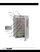
RECEIVING YOUR INCUBATOR (CONTINUED) SCO31 Control Panel CO2 Inlet CO2 Sample Port Data Jacks USB-Style Port OTL Temperature Probe (Top) Controller Board Temperature Probe (Bottom) Incubation Chamber Power Inlet, Circuit Breaker, and Data Plate Door Gasket Incubator Door 9|Page
RECEIVING YOUR INCUBATOR (CONTINUED) RECORDING DATA PLATE INFORMATION The data plate contains the incubator model number and serial number. Record this information for future reference. On the SCO58 the data plate is located on the back of the unit, on the top right side. On the SCO31 and SCO40 the data plate is toward the bottom and back of the unit’s right side.
INSTALLATION AMBIENT CONDITIONS The SCO Incubators are intended for use indoors, at room temperatures between 15C and 30C (59F and 86F), at no greater than 80% Relative Humidity (at 25C / 77F). Allow a minimum of 4 inches (10cm) between the incubator and walls or partitions, and 2 inches (5cm) of clearance above the top of the incubator for unobstructed airflow. Operating the unit outside of these conditions may adversely affect the temperature range and stability.
INSTALLATION (CONTINUED) LIFTING A SCO Incubator should only be lifted by its bottom surfaces using proper heavy lifting machinery such as, a forklift or pallet jack. Handles and knobs are inadequate for lifting or stabilization. The unit should be completely restrained from tipping during lifting. Transporting the unit while lifted is not recommended and may be hazardous. Remove all moving parts, such as shelves and trays, and secure the door in the closed position prior to lifting the unit.
INSTALLATION (CONTINUED) CONNECT THE CO2 SUPPLY TO THE INCUBATOR Note: Always use medical grade CO2. Use of non-medical grade CO2 risks introducing contaminants into the chamber, may damage the incubator, and will void the incubator’s warranty. Always install the in-line filter provided with the unit tubing kit between the gas source and the incubator. The filter is directional. Make sure that it is installed correctly with the side stamped “IN” facing toward the supply source.
INSTALLATION (CONTINUED) SHELVING INSTALLATION Shelves should be installed evenly spaced in the incubation chamber to obtain the best temperature uniformity. For ease of installation, Sheldon Manufacturing recommends that two people lift and install each shelf in the SCO58 Incubator. 1. Squeeze each shelf clip when installing. Insert the top tab first into shelf mounting standard, and then the bottom tab using a rocking motion. a. SCO58, install six (6) clips for each shelf.
INSTALLATION (CONTINUED) CLEANING AND DEIONIZED WATER The incubator interior was cleaned at the factory but not sterilized. See the Cleaning topic in the User Maintenance section for more information. Never use deionized water for cleaning the incubator! While DI water is useful in variety of laboratory applications, it is an aggressive solvent that attacks most metals. Use of DI water in a Shel Lab incubator voids the unit’s warranty.
GRAPHIC SYMBOLS The incubator is provided with multiple graphic symbols on its exterior and internal surfaces. These symbols identify hazards and the functions of the adjustable components, as well as important notes in the user manual. Symbol Definition Indicates that you should consult your service manual for further instructions. Indique que l'opérateur doit consulter le manuel d'utilisation pour y trouver les instructions complémentaires.
GRAPHIC SYMBOLS (CONTINUED) Symbol Definition Indicates Potential Shock Hazard Signale danger électrique WEEE Directive compliant logo Indicates the unit should be recycled (Not disposed of in land-fill) Indique l’appareil doit être recyclé (Ne pas jeter dans une décharge) Indicates CO2 Gas Indique gaz CO2 Indicates carbon dioxide gas content as a % Indique le gaz carbonique contenu en % 17 | P a g e
CONTROL PANEL OVERVIEW Control Panels: SCO58 Top, SCO40 SCO31 Bottom Power Switch The main power switch on the control panel controls all power to the unit and its systems. The switch illuminates when in the I on position on the SCO58.
CONTROL PANEL OVERVIEW (CONTINUED) Over Temperature Limit Thermostat (OTL) This control is marked SET OVER TEMPERATURE or Set Over Temp Safety and is equipped with a graduated dial. The OTL is a mechanical backup system that operates independently of the digital temperature controller. It guards against a failure of the digital controller that would allow the chamber temperature to rise past the controller set point.
OPERATION THEORY OF OPERATION Heating and CO2 Control The incubator uses a microprocessor controller board wired to a solid state temperature probe, a heating element located in a recirculation duct, as well as a blower fan in the duct, to monitor and regulate the temperature within the incubation chamber. SCO Incubators rely on natural heat radiation for cooling.
OPERATION (CONTINUED) Accessory Compatibility Make sure that any accessory equipment you will be using inside the incubator can safely and effectively operate at your selected temperature and CO 2 set points. The Over Temperature Limit System (OTL) When set, the OTL system prevents runaway heating in the event of a failure of the microprocessor controller board or its thermometer probe by depowering the heating element whenever the temperature in the incubation chamber exceeds the OTL setting.
OPERATION (CONTINUED) PREPARING THE INCUBATOR Perform the following steps and procedures to prepare the incubator for use each time it is installed in a new location: 1. Clean and disinfect the incubator chamber. 2. Verify the workspace power supply and incubator data plate requirements match. 3. SCO58 only: Verify that the side access port plug is in place. 4. You may play the sensor probe of a temperature reference device inside the incubation chamber at this time. a.
OPERATION (CONTINUED) SET THE TEMPERATURE SET POINT Perform these steps to prepare the unit for calibration. The unit comes from the factory set to 37°C 1. Turn the Over Temperature Limit control dial clockwise to the maximum position indicated by the largest dot. This prevents the Over Temperature Limit system from interfering with the Set the Temperature Set Point and Temperature Calibration procedures. 2.
OPERATION (CONTINUED) CALIBRATE THE TEMPERATURE DISPLAY This procedure requires a temperature reference sensor device. Always use a reference device calibrated to at least 0.1°C. For best results use a digital device with a wire sensor probe. Temperature calibrations are performed to ensure that the incubator temperature display matches the actual air temperature inside the incubation chamber. Calibrate as often as required by your laboratory protocol or regulatory compliance.
OPERATION (CONTINUED) Temperature Calibration Continued 5. Place the unit in its temperature calibration mode and calibrate. a. Press and hold both the UP and DOWN arrow buttons simultaneously. b. The Temperature Display will show the letters “CO”, then begin flashing the current temperature value. c. Use the Up or Down arrows to adjust the current temperature value until it matches the reference device temperature reading. This will correct the display’s offset error. d.
OPERATION (CONTINUED) Temperature Calibration Continued 10. If the temperature readings of the incubator and the reference device still fall outside your laboratory protocol after three calibration attempts, contact Sheldon Technical Support for assistance. a. Three calibration attempts may be required to successfully calibrate units that are ±2°C or more out of calibration.
OPERATION (CONTINUED) MUTING THE AUDIBLE TEMPERATURE ALARM An audible and visual high or low deviation alarm will activate if the incubator chamber temperature deviates by 1°C above or below the temperature set point. The low deviation alarm has a delay of fifteen minutes. This delay prevents the low alarm from activating whenever the doors are opened, causing a brief drop in temperature. 1.
OPERATION (CONTINUED) CALIBRATING THE CO2 DISPLAY Note: The CO2 display and sensor come calibrated from the factory to a 5% concentration at 179 Feet (54 meters) above sea level. The calibration procedure verifies the accuracy of the CO2 reading and corrects for any measurement errors. Calibrate as often as required by your laboratory or production protocol, or regulatory requirements.
OPERATION (CONTINUED) Calibrating the CO2 Display (Continued) 3. If there is a difference between the readings, and that difference falls outside your laboratory protocol’s acceptable range, place the incubator into calibration mode by pressing and holding the CO2 Control Up and Down arrow buttons. a. The incubator CO2 display will flash the letters “CP”, and then show a blinking adjustable CO2 concentration value. Release the arrow buttons. b.
OPERATION (CONTINUED) Calibrating the CO2 Display (Continued) Reference 6. Compare the reference CO2 analyzer reading to the reading of the incubator CO2 display. a. If the reference device and the incubator display readings are the same or the difference falls within the range of your laboratory protocol, the incubator is now calibrated for CO2. 7. If the readings falls outside your laboratory protocol’s range, enter a new adjustment offset, repeat steps 3 – 6, starting on page 29. a.
OPERATION (CONTINUED) MUTING THE AUDIBLE CO2 ALARM Visual high and low deviation indicator alarms will activate if the incubator’s CO 2 level deviates 1% above or below the CO2 set point. An audible alarm will sound immediately for a high deviation. The low deviation audible alarm will sound after the visual low indicator alarm has been continually illuminated for fifteen (15) minutes. This delay prevents the alarm from sounding whenever a door opening creates a short-lived drop in gas concentration. 1.
OPERATION (CONTINUED) LOADING THE INCUBATOR Sheldon Manufacturing recommends allowing the unit to run for at least 24-hours heated to temperature and supplied with CO2 prior to loading samples after installing in a new location. Place items on the shelves inside the incubator chamber as evenly spaced as possible. Good spacing allows for maximum air circulation and a high degree of temperature uniformity.
OPERATION (CONTINUED) DATA OUTPUT CAPABILITIES The SCO Incubators generate data outputs describing temperature and CO2 percentage levels using a 4 through 20 milliamp bus analog output module. These outputs can be connected to a building management system (BMS) or other data monitoring and capture system through the use of three jacks or a USB-style port. A hardware driver and data logging software package for the USB-style port can be downloaded from the Shel Lab website.
USER MAINTENANCE Warning: Prior to any maintenance or service on this unit, disconnect the power cord from the power supply. Avertissement: Avant d'effectuer toute maintenance ou entretien de cet appareil, débrancher le cordon secteur de la source d'alimentation. If a hazardous material or substance has spilled in the incubator, immediately initiate your site’s Hazardous Material Spill Containment protocol. Contact your local Site Safety Officer and follow instructions per the site policy and procedures.
MAINTENANCE (CONTINUED) Disinfecting Disinfect the incubator on a regular basis. Perform the following steps to disinfect the workstation: 1. Turn the unit off. Carryout your laboratory, clinical, or production space disinfection protocol. 2. If possible, remove all interior accessories (shelving and other non-attached items) from the chamber when disinfecting. Disinfect all corners, the incubation chamber. Take special care when disinfecting around the temperature probes. 3.
MAINTENANCE (CONTINUED) CONDENSATION AND THE DEW POINT Relative humidity inside the incubation chamber should never be allowed to exceed 80% at 25°C. Exceeding this thresholds will likely result in condensation, possible leaks around the incubator, and may cause corrosion damage if allowed to continue for any significant length of time Condensation will appear wherever the humidity level in the incubator chamber reaches the dew point.
UNIT SPECIFICATIONS The SCO Incubator is a 115 voltage unit. Please refer to the incubator’s data plate for individual electrical specifications. Technical data specified applies to units with standard equipment at an ambient temperature of 25°C and a voltage fluctuation of ±10%. The temperatures specified are determined in accordance to factory standard following DIN 12880, respecting the recommended wall clearances of 10% of the height, width, and depth of the inner chamber.
UNIT SPECIFICATIONS (CONTINUED) CO2 Model Range All Models 0 – 20% Concentration TEMPERATURE Model Range Uniformity Stability SCO58 Ambient +8C to 60C ± 0.5 @ 37C ± 0.1C SCO40 Ambient +8C to 60C ± 0.5 @ 37C ± 0.1C SCO31 Ambient +8C to 60C ± 0.5 @ 37C ± 0.1C Model AC Voltage Amperage Frequency SCO58 115 15 50/60 Hz SCO40 115 15 50/60 Hz SCO31 115 14.
PARTS AND CONSUMABLES Description Part Number Access Port Stopper 7750570 Adjustable Foot 2700506 CO2 In-Line HEPA Filter 2800525 CO2 Tubing Kit 9710500 Door Gasket, Magnetic SCO58 48 X 68 Inches 3450585 Door Gasket SCO40 1 foot sections, requires 20 sections 3450534 Door Gasket SCO31 1 foot sections, requires 17.25 sections 3450534 Power Cord 20 Amp 2.