ECONOMY INCUBATOR SMI1E & SMI1E-2 SMI2E & SMI2E-2 Previously Designated as: EI1 & E1-2 EI2 & E2-2 11/2013 4861571 INSTALLATION AND OPERATIONAL MANUAL Sheldon Manufacturing Inc. P.O. Box 627 Cornelius, Oregon 97113 EMAIL: tech@Shellab.com INTERNET: http://www.Shellab.
TABLE OF CONTENTS SECTION 1.0 RECEIVING AND INSPECTION SECTION 2.0 GRAPHIC SYMBOLS SECTION 3.0 INSTALLATION SECTION 4.0 CONTROL PANEL OVERVIEW SECTION 5.0 OPERATION SECTION 6.0 MAINTENANCE SECTION 7.0 TROUBLESHOOTING SECTION 8.
1 Section RECEIVING AND INSPECTION Your satisfaction and safety require a complete understanding of this unit. Read the instructions thoroughly and be sure all operators are given adequate training before attempting to put the unit in service. NOTE: This equipment must be used only for its intended application; any alterations or modifications will void your warranty. 1.1 Inspection: The carrier, when accepting shipment, also accepts responsibility for safe delivery and is liable for loss or damage.
2 Section GRAPHIC SYMBOLS Your incubator is provided with a display of graphic symbols to help in identifying the use and function of the available adjustable components. 2.1 This symbol, when shown, indicates that you should consult your manual for further description or discussion of a control or item. 2.2 Indicates “AC Power” 2.3 Indicates “Heating” 2.4 Indicates ”Adjustable Temperature” 2.5 Indicates “Manual Control” 2.6 Indicates “Earth Ground Symbol” 2.
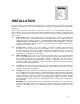
3 Section INSTALLATION Local city, county or other ordinances may govern the use of this equipment. If you have any questions about local requirements, please contact the appropriate local agency. Installation may be performed by the end user. Under normal circumstances this unit is intended for use indoors, at room temperatures between 5 above ambient to 70C, at no greater than 80% Relative Humidity (at 25C) and with a supply voltage that does not vary by more than 10%.
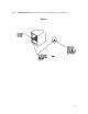
3.6 Shelf Placement: Place the two shelves in the desired position. See Figure 1.
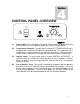
4 Section CONTROL PANEL OVERVIEW 4.1 Power Switch: The main power I/O (on/off) switch controls all power to the unit and must be in the I or ON position before any systems are operational. 4.2 Temperature Controller: The controller is marked SET TEMPERATURE and is equipped with an adjustment knob and a graduated dial. The graduated dial is marked with 10 major increments and 50 minor increments. These increments can be used as index points for setting and returning to set point temperatures. 4.
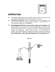
5 Section OPERATION 5.1 Check power supply against unit serial plate; they must match. Plug service cord into the grounded electrical outlet and turn the power switch ON. 5.2 Thermometer Placement: Place the thermometer and clip (provided in the accessory kit) through the hole at the top of incubator. The thermometer is to verify operating temperature. See Figure 3. 5.3 Set Temperature Controller: The temperature range for this incubator is 5C above ambient to 70C.
6 Section MAINTENANCE NOTE: Prior to any maintenance or service on this unit, disconnect service cord from the power supply. 6.1 Cleaning: Clean interior of the incubator on a regular basis. Remove shelves and shelf clips and sterilize the incubator with a disinfectant that is appropriate for your application. The shelves and clips are autoclavable, or can be cleaned with the same solution as the incubator.
7 Section TROUBLESHOOTING FOR PERSONAL SAFETY, ALWAYS DISCONNECT THE POWER BEFORE SERVICING. Always make a visual inspection of the incubator and control panel when troubleshooting. Look for loose or disconnected wires that may be the source of the trouble. TEMPERATURE Temperature too high 1/ controller set too high-see section 5.3 2/ controller failed on – call Customer Service 3/ wiring error – call Customer Service Temperature too low 1/ controller set too low – see section 5.
MECHANICAL Door not sealing 1/ check physical condition of gasket 2/ assure that gasket is in original location 3/ Verify that door latch is operating correctly and not miss-aligned or broken. OTHER Unit or wall fuse/circuit breaker is blown 1/ check wall power source. 2/ compare current draw and compare to specs on data plate. 3/ see what other loads are on the wall circuit. 4/ has the circuit breaker on the front panel been tripped? If so, see section 4.
8 Section PARTS LIST Description Circuit Breaker Fuse Fuse Holder Heating Element HEATING Pilot Lamp I/O Switch Inlet With Fuse Holder Power Cord, European Power Cord, USA Temperature Controller 115V 220V 1100505 N/A N/A 2350562 4650554 7850579 N/A N/A 1800529 1750813 N/A 3300515 3300501 2350500 4650554 7850579 4200505 1800500 N/A 1750813 12
UNIT SPECIFICATIONS Unit SMI1E (EI1) SMI1E-2 (EO1-2) SMI2E (EI2) SMI2E-2 (EI-2) Dimensions WxDxH Exterior Interior Weight Net Shipping Capacity Cubic Ft Temperature C 16.75x17.75x22.25 12x12x14 53 lbs. 44 lbs. 1.0 Amb. +5-70 21.5x18x25.5 17x12x17 71 lbs. 57 lbs. 2.0 Amb.
WIRE DIAGRAM SMI1E (E1)110V POWER CORD 1800529 FUSE POWER SWITCH 7850579 CONTROL THERMOSTAT 1750860 HEATING LIGHT 4650554 120V 250W 14
WIRE DIAGRAM SMI2E (EI2) 110V POWER CORD 1800529 FUSE POWER SWITCH 7850579 CONTROL THERMOSTAT 1750860 HEATING LIGHT 4650554 120V 250W 15
WIRE DIAGRAM SMI1E-2 (EI1-2) 220V FUSED INLET 4200505 FUSE 2800502 EMI FILTER POWER SWITCH 7850579 1 2 TOP ½ CONTROL 1750813 BOTTOM ½ CONTROL 1 1750813 2 4 4 HEATING LIGHT 4650554 125 WATTS 16
WIRE DIAGRAM SMI2E-2 (EI2-2) 220V FUSED INLET 4200505 FUSE 2800502 EMI FILTER POWER SWITCH 7850579 1 2 TOP ½ CONTROL 1750813 BOTTOM ½ CONTROL 1 1750813 2 4 4 HEATING LIGHT 4650554 120V 125 WATTS 120V 125 WATTS 17