SHELDON MICROBIOLOGICAL INCUBATORS MODELS: SMI31 SMI31-2 SMI39 SMI39-2 Previously designated as RI28, RI28-2 RI40, RI40-2 11/2013 4861573 INSTALLATION AND OPERATIONAL MANUAL Sheldon Manufacturing Inc. P.O. Box 627 Cornelius, Oregon 97113 EMAIL: tech@Shellab.com INTERNET: http://www.Shellab.
These units are TUV CUE listed as General Incubators for professional, industrial or educational use where the preparation or testing of materials is done at approximately atmospheric pressure and no flammable, volatile or combustible materials are being heated. These units have been tested to the following requirements: CAN/CSA C22.2 No. 61010-1:2012 CAN/CSA C22.2 No.
TABLE OF CONTENTS SECTION 1.0 RECEIVING AND INSPECTION SECTION 2.0 INSTALLATION SECTION 3.0 GRAPHIC SYMBOLS SECTION 4.0 CONTROL OVERVIEW SECTION 5.0 OPERATION SECTION 6.0 CHART RECORDER INSTALLATION SECTION 7.0 MAINTENANCE SECTION 8.0 TROUBLESHOOTING SECTION 9.
1 Section RECEIVING AND INSPECTION Your satisfaction and safety require a complete understanding of this unit. Read the instructions thoroughly and be sure all operators are given adequate training before attempting to put the unit in service. NOTE: This equipment must be used only for its intended application; any alterations or modifications will VOID your warranty. 1.1 Inspection: The carrier, when accepting shipment, also accepts responsibility for safe delivery and is liable for loss or damage.
2 Section INSTALLATION Local city, county or other ordinances may govern the use of this equipment. If you have any questions about local requirements, please contact the appropriate local agency. Installation may be performed by the end user. Under normal circumstances this unit is intended for use indoors, at room temperatures between 5 and 40C, at no greater than 80% Relative Humidity (at 25C) and with a supply voltage that does not vary by more than 10%.
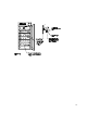
2.6 Place shelves into chamber at desired position. See Figure 1.
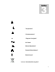
3 Section GRAPHIC SYMBOLS Your incubator is provided with a display of graphic symbols on the control panel which are designed to help identify the use and function of the adjustable components. 1. Indicates that you should consult your manual for further description and discussion of a control or user item. 2. Indicates “Temperature” 3. Indicates “Overtemperature” 4. C Indicates “Degrees Centigrade” 5. Indicates “AC Power” 6. Indicates “Manual Adjustment” 7.
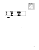
4 Section CONTROL PANEL OVERVIEW 4.1 Power Switch: The main power I/O (on/off) switch controls all power to the unit and must be in the I/ON position before any systems are operational. 4.2 Main Temperature Control: The Main Temperature Control consists of the digital display and UP/DOWN arrow pads for inputting set point temperatures and calibration. 4.3 HEATING Lamp: This green pilot lamp in ON when the unit is heating up to set point and is blinking when controlling temperature at set point. 4.
5 Section OPERATION 5.1 Check power supply against unit data plate, they must match. Plug service cord into the grounded electrical outlet, and turn the unit on. 5.2 Turn the Overtemperature Thermostat to its maximum position, clockwise, using a coin or a flat edged tool. 5.3 There are four (4) electrical outlets inside the chamber for use with electrical equipment not exceeding 1 amp. 5.4 Operating Electrical Apparatus Inside Chamber: Place the shaker, roller, spinner, etc.
6 Section CHART RECORDER INSTALLATION Please note that the following information is a general guide for installation. Chart recorders are available from your dealer. Before attempting installation please read the instructions provided with your chart recorder thoroughly for specific installation instructions. Note: Unplug unit from the power supply before installing the Chart Recorder. 6.1 Remove cover for Chart Recorder, located on the right side of control panel. 6.
7 Section MAINTENANCE NOTE: Disconnect the power cord from the power source before performing any service or maintenance on this unit. 7.1 Cleaning: Clean the incubator interior and remove and clean shelves on a regular basis. Use a disinfectant that is suitable for your application. A thorough periodic cleaning is strongly recommended. Use care when cleaning the door gasket to prevent damage which could impair the positive door seal.
8 Section TROUBLESHOOTING FOR PERSONAL SAFETY, ALWAYS DISCONNECT THE POWER BEFORE SERVICING. Always make a visual inspection of the incubator and control panel when troubleshooting. Look for loose or disconnected wires that may be the source of trouble. TEMPERATURE Temperature too high-display and reference thermometer don’t match 1/ Controller set too high-see section 5.5. 2/ Controller failed on – call Customer Service. 3/ Wiring error – call Customer Service.
3/ Check connections to sensor. 4/ Check calibration – using independent thermometer, follow instructions in section 5.6. Unit will not heat up at all 1/ Verify that controller is asking for heat by looking for HEATING light – if pilot light is not on continuously during initial start up, there is a problem with the controller. 2/ Check amperage – amperage should be virtually at maximum rated (data plate) amperage.
2/ Assure that gasket is in original location. 3/ Adjust hinge blocks or twist the door. 4/ Confirm that unit has not been damaged and body is square. Motor doesn't move 1/ If shaft spins freely: check connections to motor and check voltage to motor. 2/ If shaft rubs or is frozen, relieve binding and retest. Motor makes noise 1) Make sure that the fan or blower wheel is not contacting its housing. Adjust the motor mounting bracket position to re-center the fan or blower wheel, if necessary.
9 Section PARTS LIST Description Blower Motor Blower Wheel Cooling Fan, Control Panel Cord Set EMI Filter Fuse 10 Amp Fuse 16 Amp Heating Element, SMI31 SMI31-2 (RI28 RI28-2) Heating Element, SMI39 SMI39-2 (RI40 RI40-2) Overtemperature Thermostat I/O (On/Off) Power Switch Moisture Proof Plug Main Control w/Sensing Probe Outlet, Interior Pilot Light, Green Pilot Light, Red Shelf, SMI31 SMI31-2 (RI28 RI28-2) Shelf, SMI39 SMI39-2 (RI40 RI40-2) 115V 220V 4880548 2600535 4880564 1800510 2800503 N/A 3300513
UNIT SPECIFICATIONS Weight Shipping Net SMI31 SMI31-2 (RI28 RI28-2) SMI39 SMI39-2 (RI40 RI40-2) 610 lbs. 500 lbs. 730 lbs. 850 lbs. Dimensions Exterior WxDxH Interior WxDxH SMI31 SMI31-2 (RI28 RI28-2) SMI39 SMI39-2 (RI40 RI40-2) 38.5x34.0x75.3 30.5x26x62 41x34x87 35x26x76.5 Capacity SMI31 SMI31-2 (RI28 RI28-2) SMI39 SMI39-2 (RI40 RI40-2) Temperature SMI31 SMI31-2 (RI28 RI28-2) SMI39 SMI39-2 (RI40 RI40-2) 28 Cubic Feet 40 Cubic Feet Range Uniformity Sensitivity Amb. +8 to 70C + .
WIRE DIAGRAM SMI31 (RI28) 120V (9851242) IEC FUSED INLET 4200505 WHT BLK 2800503 BLK WHT MAIN POWER SWITCH CHERRY ROUND 7850532 BLK WHT POWER LIGHT ~ 4650554 (G) BLK BLK WHT BLK CHAMBER FAN ~ 4880548 BLK RED WHT BLU WHT BLK ½ TB1 L1 ½ TB1 L2 WHT BLK HOT TEMPERATURE CONTROL 1750982 NEUTRAL GROUND LOAD BLK BLK BLK WHT BLK OTP LIGHT 4650553 (R) 4 1 0900503 0.47 F / 250 VAC BLK HT 2 WHT HT DESIGN = 750W / 120V / 19.
WIRE DIAGRAM SMI31-2 (RI28-2) 230V (9851243) IEC FUSED INLET 4200505 WHT BLK WHT 2800503 WHT BLK MAIN POWER SWITCH CHERRY ROUND 7850532 BLK WHT POWER LIGHT ~ 4650554 (G) BLK BLK CHAMBER FAN ~ 4880548 RED ½ TB1 L1 WHT ½ TB1 L2 BLU & BLK WHT BLK HOT TEMPERATURE CONTROL 1750983 NEUTRAL GROUND LOAD BLK BLK BLK 0900503 0.
WIRE DIAGRAM SMI39 (RI40) 120V (9851244) IEC FUSED INLET 4200505 WHT BLK 2800503 BLK WHT MAIN POWER SWITCH CHERRY ROUND 7850532 BLK WHT POWER LIGHT ~ 4650554 (G) BLK BLK WHT BLK CHAMBER FAN ~ 4880548 BLK RED WHT BLU WHT BLK ½ TB1 L1 ½ TB1 L2 WHT BLK HOT TEMPERATURE CONTROL 1750982 NEUTRAL GROUND LOAD BLK BLK BLK WHT BLK OTP LIGHT 4650553 (R) 4 1 0900503 0.47 F / 250 VAC BLK HT 2 WHT HT DESIGN = 1000W 12.
WIRE DIAGRAM SMI39-2 (RI40-2) 230V (9851245) IEC FUSED INLET 4200505 WHT BLK WHT 2800503 WHT BLK MAIN POWER SWITCH CHERRY ROUND 7850532 BLK WHT POWER LIGHT ~ 4650554 (G) BLK BLK CHAMBER FAN ~ 4880548 RED ½ TB1 L1 WHT ½ TB1 L2 BLU & BLK WHT BLK HOT TEMPERATURE CONTROL 1750983 NEUTRAL GROUND LOAD BLK BLK BLK 0900503 0.47 F / 250 VAC 4 1 OTP LIGHT 6540553 (R) 4 BLK HT 2 ½ OTP 1750813 WHT HT 2 1 WHT ½ OTP 1750813 DESIGN = 1000W 58.