ECONOMY OVENS SMO1E SMO1E-2 SMO3E SMO3E-2 SMO5E SMO5E-2 PREVIOUSLY DESIGNATED AS 1321F 1321F-2 1325F 1325F-2 1327F 1327F-2 INSTALLATION AND OPERATION MANUAL Revised 12/2013 4861659 Sheldon Manufacturing Inc. P.O. Box 627 Cornelius, Oregon 97113 EMAIL: tech@Shellab.com INTERNET: http://www.Shellab.
TABLE OF CONTENTS SECTION 1.0 RECEIVING AND INSPECTION SECTION 2.0 GRAPHIC SYMBOLS SECTION 3.0 INSTALLATION SECTION 4.0 CONTROL PANEL OVERVIEW SECTION 5.0 PRECAUTIONS SECTION 6.0 OPERATION SECTION 7.0 MAINTENANCE SECTION 8.0 TROUBLESHOOTING SECTION 9.
1 Section RECEIVING AND INSPECTION Your satisfaction and safety require a complete understanding of this unit, including its proper function and operational characteristics. Read the instructions thoroughly and be sure that all operators are given adequate training before attempting to put the unit in service. Note: This equipment must be used only for its intended application; any alterations or modifications will void your warranty. 1.
2 Section GRAPHIC SYMBOLS Your oven is provided with a display of graphic symbols to help in identifying the use and function of the available adjustable components. 2.1 This symbol, when shown, indicates that you should consult your manual for further description or discussion of a control or user item. 2.2 Indicates "AC Power" 2.3 Indicates "Adjustable Temperature" 2.4 Indicates “Manual Control” 2.4 Indicates "Heating" 2.5 Indicates "Over Temperature" 2.
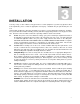
3 Section INSTALLATION Local city, county, or other ordinances may govern the use of this equipment. If you have any questions about local requirements, please contact the appropriate local agency. Installation may be performed by the end user. Under normal circumstances this unit is intended for use indoors, at room temperatures between 5 and 40C, at no greater than 80% Relative Humidity ( at 25C) and with a supply voltage that does not vary by more than 10%.
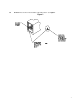
3.6 Shelves: Place shelves in the chamber at desired position. See Figure 1.
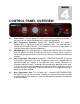
4 Section CONTROL PANEL OVERVIEW 4.1 Power Switch: The main power I/O (on/off) switch controls all power to the oven. It must be in the I or ON position before any systems are operational. 4.2 Main Temperature Controller: Marked SET TEMPERATURE, this control is equipped with an adjustment knob and a graduated dial. The graduated dial is marked with 10 major increments. The increments can be used as index points for setting and returning to set point temperatures. 4.
5 Section PRECAUTIONS This unit has been designed with a dampered vent from the chamber. In order to work effectively and safely, some precautions will need to be taken by the operator. 5.1 The bottom surface of the chamber should not be used as a work area. 5.2 In most applications, the exhaust damper will need to be open during drying or degassing for best results. 5.3 THIS OVEN IS NOT AN EXPLOSION PROOF OVEN AND IS NOT DESIGNED TO HANDLE COMBUSTIBLE GASSES.
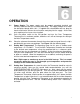
6 Section OPERATION 6.1 Power Supply: The power supply must be properly grounded (earthed) and correctly sized to match the unit data plate rating. The supply voltage must match the data plate voltage within 10%. If supplied with a detachable cord set, plug the female end into the inlet on the unit and the male plug into the supply. Assure that units requiring a fuse have a fuse installed. 6.
Figure 3 10
7 Section MAINTENANCE Note: Prior to any maintenance or service on this unit, disconnect service cord from the power supply. 7.1 Cleaning: Clean the oven interior on a regular basis. When washing interior of unit, handle gasket carefully so as not to impair the positive seal. Clean the inside of the chamber thoroughly with a disinfectant that is appropriate for your application. Make sure to rinse the cleaned surface with a damp cloth.
8 Section TROUBLESHOOTING TEMPERATURE Temperature too high 1/ controller set too high 2/ controller failed on – call Customer Service Chamber temp spikes over set point and then settles to set point Recalibrate – see section 6.3 and 6.4 Temperature too low 1/ Thermostat set too low – see section 6.5 2/ controller set too low – see section 6.
9 SECTION PARTS LIST SMO1E / SMO1E-2 (1321F / 1321F-2) Description Cord Set – European Cord Set – USA Door Gasket Door Handle Fan Fan Blade Filter Fuse Fuse Holder Heating Element Inlet with Fuse Drawer Knob, Main Temperature Knob, Over Temperature Main Temperature Controller Motor On/Off (I/O) Switch Over Temperature Thermostat Pilot Light, green Pilot Light, red Shelf Clips Shelf Thermometer Thermometer Clip 115V 220V N/A 1800510 3450722 3800610 2600502 2600545 2800502 3300516 N/A 9570746 4200505 445
PARTS LIST SMO3E / SMO3E-2 (1325F / 1325F-2) Description 115V 220V Main Temperature Control Over Temperature Control Cord Set Door Handle Heating Element On/Off Switch Knob Main Temperature Knob Over Temperature Pilot Light Green Pilot Light Red Shelf Clips Shelf Thermometer Clip Thermometer Fan Motor Fan Blade 3” Fan Blade 4.
PARTS LIST SMO5E / SMO5E-2 (1327F / 1375F-2) Description 115V 220V Main Temperature Control Over Temperature Control Cord Set Door Handle Heating Element 1327F On/Off Switch Knob Main Temperature Knob Over Temperature Pilot Light Green Pilot Light Red Shelf Clips Shelf Thermometer Clip Thermometer Filter EMI Fuse Inlet with Fuse Drawer Fuse Holder 1750863 1750615 1800516 3800610 9570778 7850570 4450528 4450506 4650554 4650553 1250511 5130714 5080865 8200509 2800502 3300516 4200505 N/A 1750863 1750648
WIRE DIAGRAMS SMO1E (1321F) 100-120V WHITE HT POWER INLET 4200505 BLACK HT 9851479 2800502 EMI FILTER BLACK HT WHITE HT GREEN LIGHTED POWER SWITCH 7850570 FAN WHITE HT FAN MOTOR 4880527 BLACK HT OTL INDICATOR 4450553 BLACK BLACK BLACK BLACK HEATING INDICATOR 4450554 4 BLACK HT 1 TEMPERATURE CONTROL 1750863 OTL 1750615 2 TAN ULTRA HT TAN ULTRA HT 550W 24Ω 16
SMO1E-2 (1321F-2) 220-240V 9851480 WHITE HT BLACK HT POWER INLET 4200505 WHITE HT 2800502 EMI FILTER BLACK HT WHITE HT BLACK HT GREEN LIGHTED POWER SWITCH 7850570 FAN FAN MOTOR 4880528 TEMPERATURE CONTROL 1750863 BLACK BLACK BLACK BLACK WHITE HT OTL INDICATOR 4450553 HEATING INDICATOR 4450554 4 4 550W 96Ω BLACK HT 2 1 TOP ½ OTL 1750648 TAN ULTRA HT TAN ULTRA HT 2 1 BOTTOM ½ OTL 1750648 17
SMO3E (1325F) 100-120V WHITE HT POWER INLET 4200505 BLACK HT 9851481 2800502 EMI FILTER BLACK HT WHITE HT GREEN LIGHTED POWER SWITCH 7850570 FAN WHITE HT FAN MOTOR 4880527 BLACK HT OTL INDICATOR 4450553 BLACK BLACK BLACK BLACK HEATING INDICATOR 4450554 4 BLACK HT 1 TEMPERATURE CONTROL 1750863 OTL 1750615 2 TAN ULTRA HT TAN ULTRA HT 750W 2350563 18
SMO3E-2 (1325F-2) 220-240V 9851482 WHITE HT BLACK HT POWER INLET 4200505 WHITE HT 2800502 EMI FILTER BLACK HT WHITE HT BLACK HT GREEN LIGHTED POWER SWITCH 7850570 FAN FAN MOTOR 4880528 TEMPERATURE CONTROL 1750863 BLACK BLACK BLACK BLACK WHITE HT OTL INDICATOR 4450553 HEATING INDICATOR 4450554 4 4 750W 76Ω BLACK HT 2 1 TOP ½ OTL 1750648 TAN ULTRA HT TAN ULTRA HT 2 1 BOTTOM ½ OTL 1750648 19
SMO5E (1327F) 100-120V WHITE HT POWER INLET 4200505 BLACK HT 9851485 2800502 EMI FILTER BLACK HT WHITE HT GREEN LIGHTED POWER SWITCH 7850570 FAN WHITE HT FAN MOTOR 4880527 BLACK HT OTL INDICATOR 4450553 BLACK BLACK BLACK BLACK HEATING INDICATOR 4450554 4 BLACK HT 1 TEMPERATURE CONTROL 1750863 OTL 1750615 2 TAN ULTRA HT TAN ULTRA HT 1000W 2350557 20
SMO5E-2 (1327F-2) 220-240V 9851486 WHITE HT BLACK HT POWER INLET 4200505 WHITE HT 2800502 EMI FILTER BLACK HT WHITE HT BLACK HT GREEN LIGHTED POWER SWITCH 7850570 FAN FAN MOTOR 4880528 TEMPERATURE CONTROL 1750863 BLACK BLACK BLACK BLACK WHITE HT OTL INDICATOR 4450553 HEATING INDICATOR 4450554 4 4 1000W 57.