SHELTER FURNACE WOOD AND COAL BURNING INDOOR FURNACE MODELS: SF2626, SF2631, SF2639 Manufactured by: Shelter Furnace 10950 Linpage Place Saint Louis, MO 63132 1-800-875-4788 REVISION I JUNE 2012 MADE IN USA Tested to UL391 Standards
SHELTER INDOOR FURNACE MANUAL MODELS: SF2626, SF2631, SF2639 SAVE THESE INSTRUCTIONS Congratulations! You have selected the finest quality wood and coal burning indoor furnace, manufactured with pride in the USA. Please take a few moments to carefully read the owner’s manual. By taking the time to familiarize yourself with your new Shelter Furnace, you will be able to look forward to years of trouble-free, dependable service. Installation: First: Check local codes.
TABLE OF CONTENTS General Information 3 Location and Installation 3 Assembly of Unit 4 Blower and Housing 4 Filter Box 5 Draft Blower 6 Draft Blower Shield 6 Fan Limit / Electrical Control Center 7 Chimney Types and Recommendations 7 Duct Runs 9 General Operation 10 Types of Wood to Use 10 First Wood Fire 11 Loading Wood 12 First Coal Fire 12 Di
General Information Laboratory testing has proven that a central solid fuel furnace provides the most viable solution to the on-going problem of homeowner utility dependence. In consideration of this fact, the Shelter Furnace has been engineered to accommodate the heating requirements of the average sized home, even during winter’s coldest months. It is constructed with high grade, heavy gauge steel and is continuously welded to assure the highest structural strength.
combustible floor. Position the furnace as close to the chimney as possible. Air for combustion must be provided into the room where the furnace is located. Allow the air free access to the furnace for combustion and ventilation. RECOMMENDATION: Purchase Chimflex™ Dry Chemical Chimney Fire Extinguisher. These are readily available at most stove shops and hardware stores. Smoke detectors should be installed on all levels of your home.
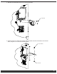
3. Assemble the following parts using 6 #10 sheet metal screws. Attach “A” (top panel) to “B” (side panel with electric) and “C” (side panel). After the top and sides are assembled, attach ”D” (bottom panel) using 6 #10 sheet metal screws provided.
5. Mount the forced draft blower with 3 ¼-20 x ½ inch bolts (provided). -- 20 1/4 20 Screw Screw 1/4-20 Screw 6. Attach the blower motor shield to the 2 brackets that are mounted on the front of the furnace, above the draft blower, using the ¼-20 x ¾ inch bolts and nuts provided.
7. Attach Fan limit with 3 #10 screws in pre-drilled holes. 8. Mount the electrical control center with 4 #10 screws (provided). Fan Limit LimitThermostat: thermostat Fan Toinstall, install,remove removethermostat thermostat To cover,attach attached cover, withwith threethree #10 #10 sheet metal screws and replace sheet metal screws and replace thermostat cover thermostat cover.
24 gauge black or blued steel. NEVER USE GALVANIZED PIPE. Horizontal run should not exceed 5 feet and should have a minimum rise of 2 inches per foot. No installation should have more than 2 elbows, a 45° elbow is recommended over a 90° elbow. As a safety precaution, all pipe selections should be fastened together with a minimum of 3 sheet metal screws.
WARNING- RISK OF FIRE: • Do not operate with flue draft exceeding .08 water column inches (19.9 Pa). • Do not operate with fuel loading or ash removal doors open. • Do not store fuel or other combustible materials within marked installation clearances. • Inspect and clean flues and chimney regularly. DANGER: Risk of Fire and Explosion. Do not burn garbage, gasoline, naphtha, engine oil, or other flammable liquids/inappropriate materials.
blower cannot be changed. This equipment should be installed, acceptable to regulatory authority, by experienced licensed personnel. The installation should comply with requirements of CAN/CSA-B365, and changes to the installation should comply with CSA-B139 (for oil-fired), C22.1 (for electric), or CAN/CGA-B149.1 or CAN/CGA-B149.2 (for gas-fired).
flue fires. NEVER burn plastics, any wood product containing glue, paraffin, or wood treated with chemical preservatives in your furnace. The combustion of these substances may release harmful, toxic gases. DANGER: RISK OF FIRE OR EXPLOSION – do not burn garbage, gasoline, naphtha, engine oil, or other flammable liquids/inappropriate materials.
period to accommodate this possibility. Your new Shelter Furnace is classified as having airtight construction. This type of design should enable you to experience an average burn time between 6 and 8 hours per full load of fuel (dry, seasoned hardwood). However, abnormally cold weather may reduce the burn time somewhat, but if your burn cycle is significantly less, for instance, 2 to 4 hours, you are over-firing your furnace.
NOTE: Do not burn coke, charcoal, highly volatile Bituminous coal, sub Bituminous, lignite or cannel coal (sometimes called channel coal or candle coal). Never burn wax or chemically processed logs, such as fire logs as their use is for fireplaces only. Please follow all guidelines in this manual concerning wood and coal burning applications due to safety concerns and to maintain warranty coverage. BURN WOOD AND COAL ONLY! Disposal of Ashes: Heat resistant gloves are recommended.
As an added precaution, periodic chimney inspections are recommended during the heating season to determine if creosote formation has occurred. For safety and efficiency, it is recommended that the chimney system be inspected and cleaned prior to each heating season. Chimney Fire Warning: In the event of a chimney fire, take the following actions immediately: • Activate and toss a ChimFlex™ Dry Chemical Chimney Fire Extinguisher into the firebox.
Furnace Diagram PARTS LIST QTY DESCRIPTION 1 ASH DOOR ASSEMBLY 12 13 11 1 ASH PAN TRAY 1 FAN SHIELD BRACKET 1 DRAFT BLOWER 1 FURNACE SHELL 1 RIGHT SIDE PANEL 1 1 1 ELECTRICAL CONTROL CENTER FAN LIMIT CONTROL FILTER BOX 1 SMOKE SLIDE DAMPER 1 BLOWER ASSEMBLY 1 TOP PANEL 1 SMOKE DAMPER ROD 1 LEFT SIDE PANEL 1 FAN SHIELD 4 1 DOOR HINGE PIN FUEL DOOR ASSEMBLY 1 AIR CONTROL DAMPER KNOB 14 10 9 15 8 16 17 7 4 3 18 1 5 6 2 PARTS LIST ITEM 1 2 3 4 5 6 7 8 9
Grate System Diagram - SF2626 2 7 1 PARTS LIST Item Description: Item Number: Total Quanti CAST RAIL 3 SLOT 2 CAST GRATE SHAKER 3 CONTROL BAR SHAKER 3 1 CONTROL BAR LINK 1 SHAKER 1 SFSCH HANDLE SHAKER CONTROL 6192 SPRHDL HANDLE SPRING 1 HTFB FIREBRICK 9.00 X 4.50 X 8 1.25 HTFB5 FIREBRICK 9.00 X 3.50 X 2 1.50 4 IS25HLN SCREW .25-20 NC X 1 HH 4 ISHH25 NUT .
Grate System Diagram - SF2639 2 1 6 8 Item: 1 2 3 4 3 5 6 7 8 9 10 9 4 5 10 ITEM 1 2 3 4 5 6 7 8 9 10 PARTS LIST Item Discription: Item Number: Total Quanti CAST RAIL 5 SLOT 2 CAST GRATE SHAKER 5 1 CONTROL BAR SHAKER 5 1 CONTROL BAR LINK SHAKER SFSCH HANDLE SHAKER CONTROL 1 6192 HTFB FIREBRICK 9.00 X 4.50 X 16 1.25 SPRHDL HANDLE SPRING 1 ISHH25 SCREW .25-20 NC X 1 HH 6 IS25HLN NUT .
WIRING DIAGRAM Wiring Diagram INDOOR FURNACE B B FAN LIMIT CONTROL ORANGE YELLOW WALL THERMOSTAT BLACK YELLOW RED RED RED RELAY 3 SPEED SWITCH 120 VAC/24 VAC TRANSFORMER RED (LOW) DRAFT MOTOR ON/OFF SWITCH 120 VAC POWER SUPPLY A WHITE BLACK BLACK (HI) 3 SPEED BLOWER MOTOR DRAFT BLOWER MOTOR 2 A WHITE BLACK GREEN BLUE (MED) 1 18
POSSIBLE blower. REMEDY CAUSE Defective Contact your supplier for replacement. REMEDY Contact your supplier for replacement. POSSIBLE CAUSE Improper wiring. POSSIBLE wiring. Review wiring diagram. If wired correctly, seek professional assistance. REMEDY CAUSE Improper Troubleshooting Review wiring diagram. If wired correctly, seek professional assistance.
REMEDY Inspect the wood for obvious signs of insect infestation such as burrows or holes, avoid using if possible. Do not store wood indoors. PROBLEM Draft blower will not run. NOTE: Verify that the wall thermostat is in the "HEAT" position, and make sure batteries are installed. POSSIBLE CAUSE REMEDY Defective rocker switch on control center.
POSSIBLE CAUSE REMEDY Improper wiring. Review wiring diagram. If wired correctly, seek professional assistance. PROBLEM Draft blower runs constantly. POSSIBLE CAUSE Defective wall thermostat. This can be checked by turning the thermostat to a lower setting than the temperature in your home. If the draft blower continues to run, the thermostat may be defective.
PROBLEM Down draft on chimney caused by one or more of the following. POSSIBLE CAUSE REMEDY Cast iron damper in "CLOSED" position. Open damper. POSSIBLE CAUSE Flue has a cold spot which inhibits exhaust discharge from rising properly. This problem may occur in factory built flues because the insulation has settled or a seam has ruptured.
PROBLEM Home does not achieve comfortable temperature. POSSIBLE CAUSE Improper ductwork connection to existing furnace. Refer to information in the manual relating to the proper installation procedures or contact your local heating and cooling contractor. REMEDY POSSIBLE CAUSE REMEDY POSSIBLE CAUSE REMEDY Excessive dirt accumulation in air filter. Check and replace filter.
Warranty Information CERTIFICATE OF LIMITED WARRANTY: EXTENT OF COVERAGE: This warranty covers any Shelter Furnace SF2626, SF2631, and SF2639 sold in the United States and Canada. This warranty applies only if the Shelter Furnace is installed, maintained, and operated in accordance with the instructions in the owner’s manual and local codes. This warranty applies to the original purchaser/owner of the Shelter Furnace and is not transferable.