
Product Manual


Page 5
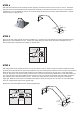
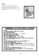
STEP 11 INSTALLING AUGER ANCHORS
Using a 3/4" pipe or steel rod, (a car tire iron works also) placed
through the eyelet on the auger, screw it into the ground. Start at
the four corners of the unit and space the remainder out evenly.
Be sure to screw the anchor in fully (the eyelet should be a level
where it can be securely attached to the frame. Wrap the cable
provided through the eyelet of the anchor and around the frame.
Secure the cable with the clamp(s) provided.
WARNING:
DO NOT INSTALL THE END PANELS OR COVER ON THE
SHELTER UNTIL IT HAS BEEN PROPERLY ANCHORED.
Page 4
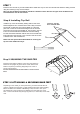
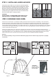
STEP 12 SECURING YOUR COVER:
* The ratchets
should be checked
monthly to make sure
the cover is tight.
Outside Corner View
Pull the cover over the frame. The welded in webbing should be at the front and back of the building. Also note that the
pocket with cutouts, running along the sides of the cover should be on the inside and near the ground. Insert the "S" hook
from the ratchets into the hole in the leg of the frame. Next, insert the webbing into the spindle of the ratchet and tighten
ratchet until the webbing overlaps itself, do not tighten all the way yet. Check to be sure the cover still has an even overhang
on the front and rear, adjust as necessary. Once the cover is even, finish tightening the ratchets, alternating from corner to
corner to ensure the cover stays even.
After the cover is tight end to end, remove the cross rails and connectors on one side of the frame and place them into
the pockets between the cutouts. Attach the crossrails using the 3-way and 4-way cover rail clamps around the uprights and
loosey fasten with the 1/4" x 1 5/8" bolts and 1/4" nuts. Check that the rails are evenly spaced above the ground on both
sides. Push down on the connectors one at a time to tension the cover and tighten the bolts to hold tightly.
Warning:
Do not leave a partially or fully covered unit without being fully anchored. Serious injury to persons or property
could result.
Fig. 11
Fig. 12
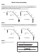
Fig. 8
corner leg
clamps
10115
1010
10112
Fig.9
middle leg
clamps
10115
10111
1010
Fig.10