
Specifications
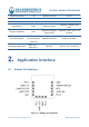
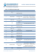
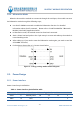
Table Of Contents

DX-BT24-T MODULE SPECIFICATION
Shenzhen DX-SMART Technology Co., Ltd. www.szdx-smart.com
- 4 -
5.3. Reflow Soldering ................................................................................................................................. - 24 -
5.4. Packing Specification ......................................................................................................................... - 25 -
Table index
Table 1 :Basic parameter table ...............................................................................................................- 6 -
Table 2 :Pin definition description table............................................................................................. - 8 -
Table 3 :Work mode table....................................................................................................................... - 9 -
Table 4 :Power interface pin definition table ...................................................................................- 10 -
Table 5 :RST pin definition table ......................................................................................................... - 12 -
Table 6 :RST pin definition .................................................................................................................... - 12 -
Table 7 :KEY Pin definition table ..........................................................................................................- 13 -
Table 8 :KEY pin function definition table ........................................................................................ - 13 -
Table 9 :Absolute maximum rating table..........................................................................................- 18 -
Table 10 :Working voltage table..........................................................................................................- 18 -
Table 11 :Working and storage temperature table ........................................................................- 18 -
Table 12 :Power consumption table ................................................................................................... - 19 -
Table 13 :RF characteristics table........................................................................................................ - 19 -
Table 14 :Table of ESD withstand voltage of module pins ...........................................................- 20 -
Table 15 :Recommended reflow soldering temperature..............................................................- 25 -
Picture index
Figure 1 :Functional block diagram ..................................................................................................- 6 -
Figure 2 :Module pin definition ......................................................................................................... - 7 -
Figure 3 :Energy-saving mode control diagram ........................................................................- 10 -
Figure 4 :Burst transmission power supply requirements .....................................................- 11 -
Figure 5 :powered reference circuit ............................................................................................... - 11 -
Figure 6 :Reset reference circuit ......................................................................................................- 12 -
Figure 7 :Key reset reference circuit .............................................................................................. - 12 -
Figure 8 :Open-collector drive wake-up reference circuit .................................................... - 13 -
Figure 9 :Key reset reference circuit .............................................................................................. - 14 -
Figure 10 :IIC communication sequence diagram .................................................................... - 15 -
Figure 11 :SPI communication timing diagram ..........................................................................- 16 -
Figure 12 :Typical application circuit ............................................................................................. - 17 -
Figure 13 :Reference circuit for serial port level conversion ................................................- 17 -
Figure 14 :Module top and side dimension drawing ...............................................................- 20 -
Figure 15 :Bottom view size of the module .................................................................................- 21 -
Figure 16 :Recommended package dimensions ........................................................................ - 21 -
Figure 17 :Top and bottom views of the module ......................................................................- 21 -
Figure 18 :Reference position for module placement .............................................................- 22 -
Figure 19 :Recommended reflow soldering temperature profile ...................................- 25 -
Figure 20 :Pallet size (unit: mm) .......................................................................................................... - 26 -
Figure 21 :Packing box size (unit: mm) ............................................................................................. - 26 -