
Specifications
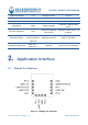
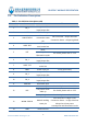
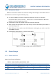
Table Of Contents

DX-BT24-T MODULE SPECIFICATION
Shenzhen DX-SMART Technology Co., Ltd. www.szdx-smart.com
- 8 -
2.2. Pin Definition Description
Table 2:Pin definition description table
Pin number Pin name Pin function illustrate
1 P0_5
Programmable
input/output line
2 UART-TX Serial data output
3 LINK-STATUS
Bluetooth
connection status
pin
Not connected:Output low level
Connection Status:Output high level
4 UART-RTS
UART request to
send, active low
5 RST
Reset
Wake up from
hibernation mode
For details, please refer to 2.5.4
6 P0_1
Programmable
input/output line
7 UART-CTS
UART clear to send,
active low
8 VBAT Power input pin 3.3V(Typical value)
9 P0_3
Programmable
input/output line
10 P0_4
Programmable
input/output line
11 UART-RX Serial data input
12 KEY
Disconnect pin For details, please refer to 2.5.5
Low power mode
wake up
For details, please refer to 2.5.5
Enter pairing mode For details, please refer to 2.5.5
13 WORK-STATUS
Module working
status pin
Not connected: 1s high 1s low
Connection Status:3s high 50ms low
Always low in low power
consumption and hibernation mode
14 GND Power Ground