Preface Vote of Thanks Thank you for buying WFLY products. The WFLY300 is the latest technology in Rotary RC models. Please read this manual carefully before assembling and flying the new WFLY300 helicopter. We recommend that you keep this manual for future reference regarding tuning and maintenance. THE MEANING OF SYMBOLS Mishandling due to failure to follow these instrudions may result in damage or i nj ury. Warning Mishandl ing due to failure to follow these instrudions may result in danger.
Features WFT06II Transmitter Applicable for: Airplane, Helicopters, Cars, Boats Frequency range: 2.400Ghz 2.438Ghz Power: ≤ 100MW Power voltage: 3.7~6.0V ≤ 190MA Great choice for entry level users Dot-matrix and segment combo LCD panel Big size LCD display Native 2.4G Flaspeed technology. Direct drived from MCU to enable high speed control. DSSS+frequency hopping system brings great anti-interference performance. 60 pcs of Wfly transmitters can be working together at the same time.
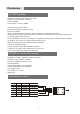
Product Configuration Please carefully check the content accessories with below check list.
Contents 3 4 6 7 8 9 10 10 11 11 12 12 12 13 13 14 15 15 16 17 17 18 18 19 19 20 20 21 21 22 22 23 24 25 26 26 27 27 28 28 29 29 Preface product description transmitter / receiver product configuration Packing list safty warnings Product diagram Front/ Back / Parts/ switchs Basic operation Edit keys / Display operation and adjustment Initial setup A Back to factory default B choose model number C choose model type D choose power supply E - training /simulator mode F - left-right hand mode G - Control stick
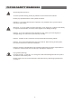
FLYING SAFETY WARNINGS Special Symbol Instruction Caution To use the product safely, please pay attention to the instruction as follows. Please pay special attention to the symbol as follows: Dangers:If you use it without proper operation, it is possible to hurt you seriously or may even cause death. Warning Warnings:If you use it without proper operation, it may make you or others to hurt badly or may even cause death, and it may cause slight hurt or damage to things.
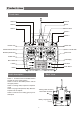
Product view Front view Switch 5 Antenna Switch 2 Buzzer Switch 1 Power switch Switch 4 Switch 3 TH.HOLD TH.CUT TIMER D/R CH 5 A:G EAR H:GY RO Elevator Trim IDLE AIL/ELE/RUD TRAIN A:CH 6 6 CH RC Radio System Throttle trim Rudder Elevator stick Aileron / Throttle stick Neckstrap attachment Aileron Trim Rudder Trim LCD Display Menu Button + Button UP button - Button Down Button Switch description Switch 1:Throttle Hold on the middle Position.
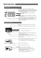
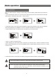
Basic operation Edit buttons Menu Button: Power on to enter stand by interface. Press and hold Menu button, enter system setting interface. In the system setting interface, press menu to switch to the next function setting. Press and hold the menu button to return to stand by interface. Up button: change the editing value towards positive direction Down button: change the editing value towards negative direction + button: to edit parameters. Press and hold the + button to fast increase the value.
Basic operation Basic operation When you want to browse or change a current setting of the transmitter, please follow the procedure as below, 1, press and hold menu button for 1 second to enter setting mode, the screen will show Menu REVR01 Initial interface Parameter setting mode Sub trim mode 2, Press Menu button, Item name will be changed according to the sequence, press until your tatended option being displayed. Eg. SUBT04 for sub trim.
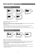
Basic operation Initial setup A Factory default Press and hold Menu button to enter setup. Press Menu button 15 times. After SYS being displayed for one second, it will shows the model number When Sure blinking, press and hold + to save. Data save will complete after WAIT being displayed for one second Press up button switch to REST to reset, press down button to confirm ●Menu display: SYS16 (helicopter mode ) - REST ●Function: SYS REST ●Function description: return to factory default setting.
Basic operation Initial setup C- choosing model Under SYS16 Press Up button switch to Model selection. Press +/- to select Heli ACRO means airplane ●Menu display: SYS 16 (helicopter mode) - HELI/ACRO ●Function: Model parameter model selection ●Function description: This transmitter support helicopters and airplane, you can select according to your model. ●Setting method: 1 press and hold Menu to enter parameter setting mode, press Menu button 15 times, till SYS 16 being displayed.
Basic operation Initial setup E Training/Simulator ●Menu display: TRSI 18 (Helicopter mode) NOR / TRA / SIMU ●Function: Training / Simulator Normal/Training mode / Simulator mode ●Function description: 1 NOR: Normal mode, RF 2.4Ghz working normally, can not work as a trainer but can be work as a trainee. 2 TRA: when this transmitter work as a trainer, the other transmitter work as a trainee through a training cable.
Basic operation Initial setup H- Coding ●Menu display: COD 21 (helicopter mode) ●Function: Coding ●Function description: this transmitter is 2.4G DSSS+hopping system, with high anti-interference performance. It is assigned with unique Address code, you need to coding with the compatible 2.4G receivers. Caution Caution: when the transmitter in Simulator mode, the screen display OFF, coding function is disabled. ●Setting method: 1, press Menu to enter COD 2, Press and hold + button to start coding.
Helicopter 01 REVR Reverse --------------------------- >> 15 02 EPA EPA setting --------------------------- >> 15 03 D/R D/R setting --------------------------- >> 16 04 SUBT Sub Trim --------------------------- >> 17 05 TSTP Trim Step --------------------------- >> 17 06 HOLD Throttle Hold --------------------------- >> 18 07 CUT --------------------------- >> 18 08 TIME Timer --------------------------- >> 19 09 NTH Normal throttle curve --------------------------- >>
Helicopter 01-REVR channel, use UP/DOWN button to change NOR/REVR, use +/- to change ●Function description Reverse setting function can be used to adjust the action direction of the channel, change the direction from normal to reverse. For Helicopters, please set the servo's direction before setting other parameters. For Airplane and gliders, please set the servo's direction after other parameters being adjusted.
Helicopter 03-D/R/EXPO Y output Y output Y output 120% 100% 60% 0% X stick position Default EPA X stick position biggest EPA X stick position EPA in small range ●Function description Both this two functions are to set 2 different value and use specific switch to activate. DR is using on Aileron elevator and rudder's control ratio, the bigger the ration, the greater the action. The greater action is suitable for maneuver. Smaller action is suitable for those with precise requirements.
Helicopter 04- SUBT sub trim ●Function description: When the trim setting is not able to achieve the necessary setting, use can use this function to further adjust the value. Please put all the TRIM in the center position to use Sub trim function. ●Setting method 1, choose SUBT 04 under setting mode 2, press UP/Down to select the CH need to be adjusted 3 press +/- button to adjust the value 4, press and hold Menu to exit or press menu to switch to next item.
Helicopter 06- HOLD Throttle hold ●Function description: During landing, use throttle hold function to fix the throttle at a low level. The range of the throttle normally set between -75% to +75%. For safety reason, when tuning the plane or helicopter on the ground, the throttle POS need to be set to -75%, and hold the throttle, to avoid any mis-operation. ●Setting method: When the setting active, use +/- button change INH (inhibit) into ON/OFF.
Helicopter 08 Time (timer) ●Function description: Timer is to allow the transmitter to alarm before your plane or helicopter exhaust the power. The largest setting is 99 minutes and 59 seconds Control method: timer ON/OFF, Throttle upper limit, throttle lower limit. Setting, TM to set minutes, TS for second, SW for switch control, THR↑for throttle upper limit, THR↓ for throttle lower limit. POS for throttle position. When timer reach 0, will beep for notification.
Helicopter 10- I TH (Idle throttle curve) ●Function description NTH Normal Throttle curve and ITH idle throttle curve are for different situation. NTH is for normal situation, ITH is for IDLE situation. Switch K4 on the upper situation is for IDLE on the lower position is for Normal situation.
Helicopter 12 GYRO Sensitivity mix ●Function description This function can be used to adjust the sensitivity of the gyro. 3 modes available in this transmitter, normal, Idle, Hold. The Gyro has the same 3 modes respectively. The greater the ratio is, the more sensitive the gyro, and vice versa. When the servo is shaking or vibrating, that means the gyro sensitivity is too high, try to lower the sensitivity till the servo back to normal.
Helicopter 14 IPI Idle pitch curve ●Function description Use this function to set the pitch curve for idle flying. The curve has 5 editable points. When idle mode is active, the idle pitch curve will optimize the engine and rotor's output. The editable value range is between 0 ~100%. Do not set the highest value over the max value that corresponding to the max engine RPM value. Normally we set to one step smaller. The minimum pitch will base on the maneuver's specific requirement.
Helicopter 16-SYS【system settings】 ●Please refer to page 11 17-BAT【Battery mode】 ●Please refer to page 11 18-TRSI【Training and simulator】 ●Please refer to page 12 19-STK【Stick Mode (Left right hand)】 ●Please refer to page 12 20-CAIL【Stick Calibration】 ●Please refer to page 12 21-COD【Coding】 ●Please refer to page 13 22-F'S【Fail safe setting】 ●Please refer to page 13 23
Airplane setting menu introduction 01 REVR Reverse setting --------------------------- >> 25 02 EPA EPA setting --------------------------- >> 25 03 D/R DR setting --------------------------- >> 25 04 SUBT SUB Trim setting --------------------------- >> 25 05 TSTP Trim step setting --------------------------- >> 25 06 HOLD Throttle hold --------------------------- >> 25 07 CUT --------------------------- >> 25 08 TIME TIMER --------------------------- >> 25 09 NTH -----
Airplane 01-REVR【reverse setting】 ●Please refer to page 15 02-EPA【EPA setting】 ●Please refer to page 15 03- D/ R【D/R setting】 ●Please refer to page 16 04-SUBT【SUB trim】 ●Please refer to page 17 05-TSTP【Trim step】 ●Please refer to page 17 06-HOLD【Throttle hold】 ●Please refer to page 18 07- CUT【throttle cut】 ●Please refer to page 18 08-TIME【timer】 ●Please refer to page 19 09-NTH【Normal throttle curve】 ●Please refer to page 19 25
Airplane 10- FLER (Flap aileron mix control) ●Function description This function is to for aileron to act like flaperon even using two servos on aileron. Due to flaperon, aileron can move up or down accordingly. Aileron differential can also be achieved. AIL 1 ↓ aileron 1 down; Ail1 aileron 1 up; Ail2 aileron 2 down; AIL2 aileron2 UP; FLP1 Flap 1; FLP2 FLAP 2.
Airplane 12 ADIF aileron differential ●Function description This function is to use to make differential for the aileron on both sides when using 2 servos. AIL1↓ Aileron 1 down AIL1↑ Aileron 1 up AIL2↓ aileron 2 down AIL2↑ AILERON2 up When turning using aileron, you will need more aileron travel on up direction. ●Setting method 1, select ADIF 12 under setting mode 2, press +/- button to switch between ON/OFF, press UP/DOWN to choose the position, press +/- to change value.
Airplane 14 ELEV elevator ●Function description This function is for the combination of elevator and aileron, allow the use of delta-wing, Guts-wing, and ailless aircraft. User can adjust the aileron and elevator separately. AIL1 ↓ aileron 1 down AIL1↑ aileron 1 up, AIL2 ↓ aileron 2 down, AIL2 ↑ Aileron2 UP ELE1 Elevator 1 ELE2 elevator 2 ●Setting method, 1, select ELEV 14 under setting mode 2, press +/- button to switch between ON/OFF, press UP/DOWN to choose the position, press +/- to change value.
Airplane 16 VTAL (v tail mix control) ●Function description This function is to combine the function of elevator and rudder when using v tail airplane. The travel of elevator and rudder can be adjusted independently. ELE1 elevator 1 ELE2 elevator 2 RUD1 rudder1 RUD2 rudder 2 ●Setting method: 1, select VTAL16 under setting mode 2, press +/- button to switch between ON/OFF, press UP/DOWN to choose the position, press +/- to change value.
www.wflysz.com shenzhen WFLY technology development Co.