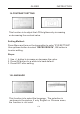
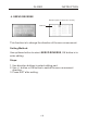
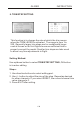
GLIDER INSTRUCTION 14.CONTRAST SETTING This function is to adjust the LCD brightness by increasing or decreasing the contrast value. Setting Method: Press Menu and turn on the transmitter to enter “SYS SETTING” Use up/down button to select “RECEIVE DATA”, OK button is to enter editing. Steps: 1. Use +/- button to increase or decrease the value. 2. Press OK button for a while is to back default. 3. Press EXIT after setting. 16.LANGUAGE This function is to select the language.
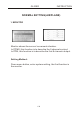
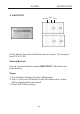
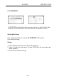
GLIDER INSTRUCTION NORMAL SETTING(AIRPLANE) 1. MONITOR Monitor shows the servos’ movement situation. In PCMS, this function is to describe the 9 channels output. In PPM, this function is to describe the first 8 channels output. Setting Method: Press menu button, enter system setting, the first function is the monitor.
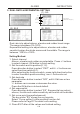
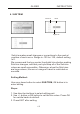
GLIDER INSTRUCTION 2. DUAL RATE & EXPONENTIAL SETTING (1). AIL Servo Switch Curve picture (please refer to Page 27) Dual rate Exponential Curve point (3). RUD (2). ELE Dual rate is to adjust aileron, elevator and rudder travel range. The range is between 0%-120%. Exponential setting is to adjust aileron, elevator and rudder sensitivity when the sticks are around the middle. The range is between -100% to +100%. Setting Method: 1. Select channel Aileron, elevator and rudder are selectable.
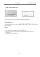
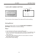
GLIDER INSTRUCTION 3. ABK. CURVE SETTING This function is used to make the glider speed down. Setting Method: Use up/down button to select ABK. CURVE SETTING, OK button is to enter editing. Steps: 1. Use direction buttons to select editing part. 2. Use +/- button or OK button to switch the servo movement direction. 3. Press EXIT after setting.
GLIDER INSTRUCTION 4. SERVO REVERSE Direction (Rev-reverse, Nor-normal) Channel This function is to change the direction of the servos movement. Setting Method: Use up/down button to select SERVO REVERSE, OK button is to enter editing. Steps: 1. Use direction buttons to select editing part. 2. Use +/- button or OK button to switch the servo movement direction. 3. Press EXIT after setting.
GLIDER INSTRUCTION 5. END POINT Channel Side Value It is to adjust the end of individual servo’s travel. The range is from 0% to 120%. Setting Method: Use up or down button to select END POINT, OK button is to enter editing. Steps: 1. Use direction buttons to select editing part. 2. Use +/- button or OK button to set the travel value. Press OK for a while backs to default. 3. Press EXIT after setting.
GLIDER INSTRUCTION 6. SUB TRIM Channel Value High/Low Sub trim makes small changes or corrections to the neutral position of each servo. Range is -120 to +120, default setting is 0. We recommend that you center the digital trims before making Sub trim changes, and that you tryto keep all of the Sub trim values as small as possible. Otherwise, when the Sub trims are large values, the servo’s range of travel is restricted on one side.
GLIDER INSTRUCTION 7. AUXILIARY CHANNELS SETTING Channel Switch Direction This function is for channel 5 to channel 9 function setting. Setting Method: Use up or down button to select AUXILIARY CHANNELS SETTING, OK button is to enter editing. Steps: 1. Use direction buttons to select editing part. 2. Use +/- button to set the switches or knobs. The switches can be set from A to F, the knobs can be set as VA, VB, VC, VL, VR or none(-). 3.
GLIDER INSTRUCTION 8. TRIM STEP SETTING This function is to change the rate at which the trim moves when the TRIM LEVER is activated. The range is from 1to 250. Generally larger trim steps are for models with larger control throws or for first flights to ensure sufficient trim to properly correct the model. Smaller trim steps are later used to allow very fine adjustments in flight. Setting Method: Use up/down button to select TRIM STEP SETTING, OK button is to enter editing. Steps: 1.
GLIDER INSTRUCTION 9. FLAPERON FLAPERON mixing function uses on servo on each of the two ailerons, and uses them for both aileron and flap function. Setting Method: Use up/down button to select FLAPERON, OK button is to enter editing. Steps: 1. Use direction buttons to select editing part. 2. Use +/- button to set value. Press OK button for seconds can back default. 3. Press EXIT after setting.
GLIDER INSTRUCTION 10. FLAP TRIM FLAP TRIM assigns the primary flaperon control to allow trimming in flight of the flap action of flaperons. Setting Method: Use up/down button to select FLAP TRIM, OK button is to enter editing. Steps: 1. Use direction buttons to select editing part. 2. Use +/- button to set value. Press OK button for seconds can back default. 3. Press EXIT after setting.
GLIDER INSTRUCTION 11. AIL-DIFF Aileron differential(AIL-DIFF) is primarily used on 3-servo wings, with one servo operating inboard flap(s) on Ch6, and AIL-DIFF controlling proper aileron operation of 2 aileron servos, plugged into Ch1 and Ch7. Setting Method: Use up/down button to select AIL-DIFF, OK button is to enter editing. Steps: 1. Use direction buttons to select editing part. 2. Use +/- button to set value. Press OK button for seconds can back default. 3. Press EXIT after setting.
GLIDER INSTRUCTION 12. ELEV-FLAP ELEV-FLAP mixing is the first pre-programmed mix we’ll cover. This mix makes the flaps drop or rise whenever the elevator stick is moved. It is most commonly used to make tighter pylon turns or squarer corners in maneuvers. In most cases, the flaps droop (are lowered) when up elevator is commanded. Setting Method: Use up/down button to select ELEV-FLAP, OK button is to enter editing. Steps: 1. Use direction buttons to select editing part. 2. Use +/- button to set value.
GLIDER INSTRUCTION 13. FAIL SAFE This function is to set responses in case of loss of signal or low RX battery. Setting Method: Use up/down button to select FAIL SAFE, OK button is to enter editing. Steps: 1. Use direction buttons to select editing part. 2. Use +/- button to select “hold” or “0.0%” 3. Press OK button to confirm the current parameter. 4. Press EXIT after setting.
GLIDER INSTRUCTION 14. TIMER The flight time of every helicopter is different according to the different tank of fuel, engine, ESC, etc. Timer function can alarm you to land before the fuel lacks. The transmitter can set 3 timers (A, B, C). The longest time can be set as MM99SS59. The countdown timer can alarm user before 10 minutes. The alarm will become 2S/1S from 1S/1S in the last 10 seconds. When the countdown timer is 0, the time will add up. The timer can be seen in the opening screen.
GLIDER INSTRUCTION 15. Language This function is to select the language. There are 5 language selectable. For example, the selection is as shown in the picture.
GLIDER INSTRUCTION 16. ADVANCED To realize an idea fly, there are 20 advanced function in ADVANCED. Setting Method: Use up/down button to select ADVANCED, OK button is to enter editing. +/- button can turn page. About each advanced functions please read the following pages.
GLIDER INSTRUCTION ADVANCED function introduction (1). CURVE SETTING There are 2 kinds of setting, Normal and Advanced. Please refer to page 27.
GLIDER INSTRUCTION (2)-(8). PROG. NOR. MIX1-7 The mix program is to adjust the flying pose. There are 7series programs with the same setting method. You can set one mix and one mix with another one mix. Setting Method Use up/down button to select PROG. NOR. MIX, OK button is to enter editing. Steps: 1. Use direction buttons to select editing part. Set any two channels mix. 2. Use +/- button to active or inhibit “Mix”. 3. Use +/- button to active or inhibit “Link” and “TRIM”. 4.
GLIDER INSTRUCTION (9)-(12). PROG. CUR. MIX1-4 There are 4 curve mix program, the curve is made up by 2 to 10 point. Setting Method: Use up/down button to select PROG. CUR. MIX, OK button is to enter editing. Steps: 1. Use direction buttons to select editing part. Set any two channels mix. 2. Use +/- button to active or inhibit “Mix”. 3. Use +/- button to active or inhibit “Link” and “TRIM”. 4. Use +/- button to active or inhibit “CTRL“. 5. Use +/- button to set the control switch position. 6.
GLIDER INSTRUCTION (13). BUTTERFLY AIR BRAKE simultaneously moves the flaps, twin ailerons and elevators, and is usually used to make steep descents or to limit increases in airspeed in dives. Setting Method: Use up/down button to select AIR BRAKE, OK button is to enter editing. Steps: 1. Use direction buttons to select editing part. 2. Use +/- button to active or inhibit “Mix”. 3. Use +/- button to set Swit, POSI. Press OK button for seconds can back default. 4. Use +/- button to set CTRL (MAN/ THR). 5.
GLIDER INSTRUCTION (14). ELEVON This function used with delta wings, flying wings, and other tailless aircraft that combine aileron and elevator functions, using two servos, one on each elevon. The aileron/elevator responses of each servo can be adjusted independently. Setting Method: Use up/down button to select ELEVON, OK button is to enter editing. Steps: 1. Use direction buttons to select editing part. 2. Use +/- button to set value. Press OK button for seconds can back default. 3.
GLIDER INSTRUCTION (15). AILVATOR AILEVATOR mixing function uses one servo on each of the two elevators, and combines the elevator function with the aileron function(unless aileron travel is set to 0). Setting Method: Use up/down button to select AILVATOR, OK button is to enter editing. Steps: 1. Use direction buttons to select editing part. 2. Use +/- button to set value. Press OK button for seconds can back default. 3. Press EXIT after setting.
GLIDER INSTRUCTION (16). V-TAIL V-TAIL mixing is used with v-tail aircraft so that both elevator and rudder functions are combined for the two tail surfaces. Both elevator and rudder travel can be adjusted independently on each surface. Setting Method: Use up/down button to select V-TAIL, OK button is to enter editing. Steps: 1. Use direction buttons to select editing part. 2. Use +/- button to set value. Press OK button for seconds can back default. 3. Press EXIT after setting.
GLIDER INSTRUCTION (17). START OFS This function is used to offset the aileron, elevator, and flap servos to the position that provides maximum lift during launch. Normally the ailerons and flaps are drooped about 20-30, with the flaps drooped slightly more to prevent tip-stailing on tow. The elevator can also be offset in oo trim out any pitch changes caused by the flap and aileron presets. Setting Method: Use up/down button to select START OFS, OK button is to enter editing. Steps: 1.
GLIDER INSTRUCTION (18). SPEED OFS This function is used to offset the aileron, elevator, and flap servos for minimum drag in cruise and high-speed flight. Normally the ailerons and flaps are raised about 3-5. Setting Method: Use up/down button to select SPEED OFS, OK button is to enter editing. Steps: 1. Use direction buttons to select editing part. 2. Use +/- button to active or inhibit this function. Press OK button for seconds can back default. 3. Press EXIT after setting. (19).
INSTRUCTION TO THE PILOT Is the 2.4G version which includes helicopter, airplane and glider function. Thank you for using the radio systems. We welcome your valuable advice and we will continue developing the radio. Welcome to contact us! Www.wflysz.com sales@wflysz.
FCC WARNING This device complies with Part 15 of the FCC Rules. Operation is subject to the following two conditions: (1) this device may not cause harmful interference, and (2) this device must accept any interference received, including interference that may cause undesired operation. NOTE 1: The manufacturer is not responsible for any changes or modifications not expressly approved by the manufacturer for compliance, such modifications could void the user’s authority to operate the equipment.