9"LCD MONITOR REV A User Manual 19" LCD Monitor HL1926
19" LCD MONITOR REV A Contents 1. Application........................................................................................................................................................................1 2. Declarations ......................................................................................................................................................................2 Safety precautions .............................................................................................
19"LCD MONITOR REV A Federal Communications Commission (FCC) Statement You are cautioned that changes or modifications not expressly approved by the part responsible for compliance could void the user’s authority to operate the equipment FCC- Class B This equipment has been tested and found to comply with the limits for a Class B digital device, pursuant to part 15 of the FCC Rules. These limits are designed to provide reasonable protection against harmful interference in a communications.
19" LCD MONITOR REV A 2. Declarations Safety precautions E232196 Medical Equipment With respect to electric shock, Fire and mechanical hazards only in accordance with UL 60601-1 and CAN/CSA C22.2 No. 601.1 Regular maintenance and calibration are recommended Please note that liquid crystal displays such as the HL1926 do not have a failure rate of zero and image parameters may change over time (e.g. luminance or discoloration).
19" LCD MONITOR REV A Only use a perfect power supply cable A damaged power supply cable may result in a fire or electric shock. When disconnecting the power supply cable, always do so by holding the plug. Only use the same type of fuse T2A/250V Do not insert any objects into the housing Objects inserted into the housing may result in damage to the unit or personal injury. Do not place any objects on top of the units Penetrating liquids may result in a fire or electric shock.
19" LCD MONITOR REV A Only use the signal cables and interface cables specified by the manufacturer for the installation. Use power cables with a PE contact. Only insert into sockets with a PE contact. For certain applications, the video earth can be separately connected to the PE via the additional PE connection in the plug panel (observe IEC 601-1-1). Close the plug panel using the provided cover (meaning the display stand), and secure using the screws. Turn switch off and then remove power cord.
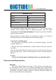
19" LCD MONITOR REV A Mounting screws Number 4 Thread M4 Strength 12 Immersion depth Min. 10 mm; Max. 12 mm Torque Max. 3 Nm The permissible ambient temperature range (5 °C ... 40 °C) must not be violated. Do not subject device to unnecessary shocks. Take care when transporting! Use the original packaging! The panel in particular should be protected against shocks.
19" LCD MONITOR REV A Lamp Disposal Hg Lamp(s) inside this product contains mercury and must be recycled or disposed of according to state, local or federal law. For more information, Contact the electronic industries alliance at www.Elae.org. For lamp specific disposal information check www.lamprecycle.org.
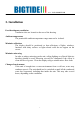
19" LCD MONITOR REV A 3. Installation Provide adequate ventilation Ventilation slots are located on the rear of the housing. Ambient temperature The permissible ambient temperature range must not be violated. Minimize reflections The display should be positioned so that reflections of lights, windows, furniture with shiny surfaces or light-colored walls do not appear on the screen. Minimize mirroring In order to reduce mirroring on the unit, ceiling lighting or reflected light (no dazzling) should be used.
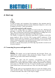
19" LCD MONITOR REV A 4. Start-up Caution In order to ensure safe operation of the equipment, close attention must be paid to the information contained in this Instruction Manual as well as the warnings in Section 2 "Safety precautions". Caution Information for end customer None of the settings must be changed on site by the user, otherwise the guarantee is canceled. This also applies to settings made using the HL1926 keys. These are therefore locked for certain applications.
19" LCD MONITOR REV A 4.1.1 Little cover (removing) Remove the one screws with an M4 Slot screwdriver (two turn suffices). Open the little cover and remove it 4.1.
19" LCD MONITOR REV A Connect the cables to the display. To remove the power cable ,first remove the strain relief .It is used for protecting the connection. As the following figure shows. When fixing the power cable, reverse the steps. 15-pin Sub-D connector: the flat panel display can be connected to the computer system using the Sub-D connector. The display is adapted using an OSD menu.
19" LCD MONITOR REV A 4.1.3 Little cover (attaching) Lead the monitor end of the cables through the little cover’s cable duct. Connect the little cover to the rear cover. 4.2 Switching on the display Switch on the flat panel display using the power switch. The operation LED lights up (color: green, provided the timing has been recognized – please refer to section 7 "Fault diagnostics"). 4.
19" LCD MONITOR REV A lighting, adjust the backlight brightness (note: 137 cd/m² factory setting is then modified). 4.5 Screen saver A screen saver function should be used in order to reduce "image sticking" which can occur in TFT displays. It is high risk to display a static graphic over half an hour. Image sticking is the effect where a faint image of the previous screen contents can still be seen after the display contents have changed.
19" LCD MONITOR REV A 5. Connections 5.1 Connecting the flat panel display Note All screening precautions contained in the corresponding EMC guidelines must be observed. If these guidelines are not observed, interference signals could penetrate the monitor. Information on cable installation Only screened cables are permitted for the signal connections. All connectors should be of screw or locking types (as far as possible). Signal and power cables must not be routed in the same duct.
19" LCD MONITOR REV A 5.4 Analog and digital inputs (DVI-D, VGA) 15-pin Sub-D connector Connect VGA cable with 15-pin Sub-D connector (male) for the analog input to the 15-pin Sub-D connector (female). With DVI-I analog signal (connected with DVI-I to VGA converter) DVI socket With DVI digital signal. 5.5 Power supply connection Note Device fuses can not be exchanged outside of the repair centers. The display power supply is connected using an appliance plug.
19" LCD MONITOR REV A 6. Adjustments 6.1 Picture adjustment This section describes the settings for operation of the flat panel display with a video source. The most important settings are: Adjusting the graphics memory of the video source As with all monitors, the flat panel display also has certain limits, e.g. maximum resolution and vertical frequency. The graphics adapter must be set when using the flat panel display such that the limits are observed.
19" LCD MONITOR REV A slightly until the display is just above the absolute lowest black level (one step is generally sufficient). Similarly, set the white level using a 100%-white test pattern and the measurement device. Only the contrast level should be adjusted to ensure that the black level remains unchanged. • Control again the black value did not change. In case it did you need to duplicate the two previous steps until it does not change anymore (cause: pedestal).
" LCD MONITOR REV A 6.3 OSD menu 6.3.1 Keys assignment and operation LED Auto Menu + - Exit A “dynamic help for keypad function” is available for each menu: it explains the role of each key depending on the OSD menu window, which is currently active. 6.3.
19" LCD MONITOR REV A * Scenario in case all signal sources is available. If not, the signal from the next available source will be displayed. 6.3.
19" LCD MONITOR REV A 6.4 Description of the menus Main Menu Brightness /Contrast Function Backlevel Contrast Backlight Color Adjustment range Description 0…255 It is used to adjust the black level of the monitor. The center point is in 128 position. This allows the darker area to be seen more distinctly. Note: for DVI-D signals the brightness setting is optimized. Manual changes are not recommended. 0…255 Adjustment of contrast This allows the brighter area to be seen more distinctly.
19" LCD MONITOR REV A Position (Analog input only) Set user color Red Gain 0…255 Green Gain Blue Gain Red bias -50…50 Green bias Blue bias Define user color temperature Select Red, Green, Blue gain and Red, Green, Blue bias separately. The default state is in 255 position and color 1 state. Red, Green, Blue gain are used to adjust white color temperature. Red, Green, Blue bias are used to adjust Red, Green, Blue bias separately. It is used adjust the dark color temperature.
19" LCD MONITOR REV A Language Execute selected auto function The selected auto functions are executed. Note: The quality of the function depends on the applied picture contents. To get better effect it is recommended to apply full screen and including whiteness contents picture. Auto Adjust On Mode Change Enable or disable automatically get input signal match with the monitor, when the signal mode is changed English Chinese Select the language of OSD menu. Note: English menu is default state.
19" LCD MONITOR REV A DPMS setting DPMS on The backlight is switched off while it is no input signal. (The default state is DPMS on) DPMS off The backlight will not switch off if it is no input signal. Only switches off along with the power switches off. Status Service Level2 Current display settings can be called here in the respective picture mode.
19" LCD MONITOR REV A 7.
19" LCD MONITOR REV A 8. Technical data All technical data are valid after a warming-up period of 2 hours. 8.1 Display Type Display area Picture diagonal Native resolution Pixel organization Pixel pitch Contrast ratio Horizontal viewing angle Vertical viewing angle Backlight Brightness Lifetime backlight TFT, color active matrix 376 mm x 301 mm 19" or 48 cm 1280 x 1024 (full-screen format) 3 vertical sub pixels 0.294 mm x 0.
19" LCD MONITOR REV A 8.3 Electronics Multi-standard technology Timing recognition Video modes with resolutions less than 1280 x 1024 can be expanded to the TFT resolution, and thus utilize the full display area (like multi-sync CRTs). In the same way, resolutions higher than 1280 x 1024 can be reduced and then displayed.
19" LCD MONITOR REV A 8.4.3 Serial interface RS232 Via D-sub 9pin 8.4.4 Timing Input Input Signals Analog Digital Horizontal frequency 31kHz -82kHz 31kHz -82kHz Vertical frequency 50.0Hz - 85.0 Hz (Non-Interlaced) 50.0Hz - 85.0 Hz (Non-Interlaced) Video Signal Analog RGB Digital RGB Sync. Signal Separate Sync. (TTL) Composite Sync. Sync on green TMDS Input connector Mini D-sub 15Pin DVI-D 8.
19" LCD MONITOR REV A 8.6 Mechanical design Housing components plastic Protective screen No Visible screen surface Approx. 376 mm x 301 mm Ventilation slots In rear panel Degree of protection (front) IP20 to DIN 40 050 Connection panel At rear, covered Weight: Without stand 10.3 kg (approximate) Dimensions (W x H x D) in mm Without stand 435 x 365 x 82mm 8.7 Climatic conditions Operation Ambient temperature range Temperature gradient Relative Humidity Atmospheric pressure +5 ...
19" LCD MONITOR REV A 8.8 Mechanical requirements Operation Vibration Shock According to EN 60068-2-6 10 ... 58 Hz with ± 0.075 mm deflection 58 ... 500 Hz at 10 m/s² According to EN 60068-2-27 (single shock) 150 m/s², 6 ms No permanent shock allowed in operating conditions Packed unit Vibration According to EN 60068-2-6 5 ... 9 Hz with ± 3.5 mm deflection 9 ...
19" LCD MONITOR REV A 8.10 Electromagnetic compatibility EMI voltage/ radiated interference Voltage variations EN 60601-1-2 EN 610004-11 EN 61000-4-4 Burst on power supply lines 1 kV EN 61000-4-5 Surge on power supply lines 1 kV symmetric 2 kV unsymmetric Static discharge on casing parts EN 61000-4-2 (ESD) 8 kV air, 4 kV contact EN 61000-4-3 RF irradiation 80 MHz ... 2,5 GHz 3 V/m 80% AM 1 kHz EN 61000-4-6 Noise immunity 150 kHz ... 80 MHz 3 Veff 80% AM 1 kHz EN 61000-4-8 Magnetic constant fields Max.
19" LCD MONITOR REV A 9. Dimensional drawings All dimensions in mm. 9.
19INCH LCD MONITOR FOR MEDICAL REV A 10 Remarks and contact address Invalidity of guarantee All unauthorized electrical or mechanical alterations on or in the unit result in loss of the guarantee. Information on the Instruction Manual For clarity reasons, this Instruction Manual does not contain all detailed information on this product.