
User's Manual


Page 15 of 29
2 D-
3 D+
4 GND
6. Adjustments
6.1 Picture adjustment
This section describes the settings for operation of the flat panel display
with a video source. The most important settings are:
Adjusting the graphics memory of the video source
As with all monitors, the flat panel display also has certain limits, e.g.
maximum resolution and vertical frequency. The graphics adapter must be
set when using the flat panel display such that the limits are observed.
Fine adjustment of the flat panel display
Note
Fine adjustment of the flat panel display can only be carried out via the
analog port. The digital input (DVI-D,DP) does not require a fine adjustment
since the display signal is always optimum.
RGB picture sources via VGA connector supply analog signals which are
basically intended for conventional CRT monitors and which are processed
directly by them.
In contrast, the analog signals must be converted for a flat panel display
into digital signals by a video digitizer. Depending on the picture source,
cable length and video mode (e.g. VGA, SVGA, XGA) this conversion may
cause certain deviations which cannot be corrected fully automatically by
the flat panel display. A manual fine adjustment is therefore necessary
during which the flat panel display (or, more precisely, the video digitizer) is
matched to the respective video source. The fine adjustment comprises e.g.
setting the horizontal/vertical picture position and the picture sharpness.
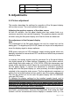
This can be carried out for the color flat panel display HL1916 SERIALS
using an OSD menu.
To optimize the display settings for the installed graphic board, and to
ensure all gray levels are distinguishable, we recommend to adjust the
brightness and contrast levels for and only for analog inputs. Note that the
calibration (in the Look Up Table) is not changed by these adjustments (All
the monitors are and remain factory calibrated):
Using a 100% black picture and an appropriate measurement device (a
spot meter recommended), decrease the brightness level using the OSD
controls until the measurement device displays a constant level (i.e. the