The users manual or instruction manual for an intentional or unintentional radiator shall caution the user that changes or modifications not expressly approved by the party responsible for compliance could void the user's authority to operate the equipment.
TABLE OF CONTENTS INTRODUCTION Notice Approval Information Restrictions Maintenance PRODUCT Package Contents Feature Locations Adapter 1~3 1 2 3 3 4~6 4 5 6 INSTALLATION & USAGE 7~12 Installation Fix the Camera Camera Channel Setup Night Vision Receiver Mode Setup 7~8 9 10 10 11~12 SPECIFICATIONS 13 TROUBLESHOOTING 14 EU Environmental Protection Waste electrical products should not be disposed of with household waste. Please recycle where facilities exist.
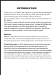
INTRODUCTION Thank you for your interest and support in our product and purchasing this wireless camera kit. This product works at ISM-2.4GHz frequency band, which could be legally used worldwide without permission. We feel confident that you will be pleased with the quality and features of this product. The camera is made of alloyed shell and special weather-proof enclosure that protect it against powder and water sprays. It passed the IP54 testing.
Approval Information All our products meet the requirements of approval FCC, and are granted the FCC certification. They are authorized to bear FCC mark. This equipment has been tested and found to comply with the limits for a Class B digital device, pursuant to Part 15 of the FCC rules. These limits are designed to provide reasonable protection against harmful interference in a residential installation.
Restrictions 1. DO NOT use this product to violate one's privacy. Monitoring one's activities without consent is illegal and this product is not designed and manufactured for such purpose; 2. DO NOT put this product near any medical equipment. Radio waves might potentially cause breakdown of electrical medical equipment. So this product should be placed at least 1 feet away from any heart pacemaker. Radio waves might potentially influence heart pacemaker and lead to respiratory disturbance; 3.
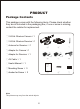
PRODUCT Package Contents This package comes with the following items. Please check whether they are all included in the packaging box, if one or some is missing, contact the retailer for replacement. ① 2.4GHz Wireless Camera×1 ② 2.4GHz Wireless Receiver×1 ③ Antenna for Receiver ×1 ① ② ③ ④ ⑤ ⑥ ⑦ ⑧ ⑨ ④ Adapter for Camera×1 ⑤ Adapter for Receiver ×1 ⑥ AV Cable ×1 ⑦ User's Manual × 1 ⑧ Mounting Screw × 3 ⑨ Anchor for Screw × 3 Note: The pictures may vary from the actual objects.
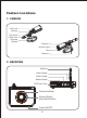
Feature Locations 1. CAMERA MIC Hole Antenna Dip Switch Power Jack Universal Bracket Fastener 2 Infrared Lights Lens Fastener 1 2.
Adapter This product always conforms to the authenticated AC adapter.
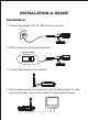
INSTALLATION & USAGE Installation 1. Connect the adapter (DC 8V 300mA) to the camera. 2. Set the camera to one desired channel. Default Setting Channel Switch 3. Connect the antenna to the receiver. 4. Connect the receiver to a monitor/TV with AV cable (yellow for video and red for audio). Turn on the monitor/TV and select AV mode.
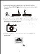
5. Connect the power jack of adapter (DC 7.5V 300mA) to receiver. Press the Power ON/OFF " " button and the channel indicator lights up green. Power ON/OFF Button 6. Press the Channel Select Button "CH" on the receiver until the channel indicator matches to the channel on the corresponding camera, and the monitor/TV will display pictures. Channel Select Button “CH" 7. Adjust the brightness, contrast and color of the monitor/TV for the perfect effect.
Fix the Camera 1. Locate the camera Please follow the steps below if you want to fix the camera to wall or ceiling. 1.1 Secure the three screw anchors into wall (or ceiling) according holes in the camera bracket; 1.2 Align holes in the camera bracket and the anchors, and locate the camera on the wall with three screws. Screw anchors 1.1 1.2 2. Adjust the angle 2.1 Unscrew Fastener 1, adjust the camera to an appropriate angle, and then fasten it. 2.
Camera Channel Setup This camera has 4 selectable channels to avoid possible interference from other nearby wireless devices. Default Setting Channel Switch Channel Switch Setup Diagram Channel Frequency CH1=2,414MHz; CH2=2,432MHz; CH3=2,450MHz; CH4=2,468MHz Night Vision The built-in Infra-red lights in camera provide 7m night vision range for 24hrs surveillance. The Infra-red lights will be automatically activated at night or in dark places.
Receiver Mode Setup The receiver can support up to 4 cameras working at the same time. You are allowed to set the Mode Control as described below. The Mode Control has the precedence over other buttons.
Channel-scan Set ON CHANNEL M M: Manual Mode (Default) L: Channel-scan Mode OFF 1. Manual mode: Slide Mode Control switch to M to enter Manual mode. In this mode, the receiver channel won't change until you press the Channel Select Button "CH"; Tip: You could also activate channel-scan function by pressing and holding the Channel Select Button "CH" more than 5s at Manual mode and deactivate it by pressing the button again.
SPECIFICATIONS Items Value Transmission Frequency ISM 2,400MHz~ 2,483MHz Antenna Type Omni Transmission Distance 100m (Without Block) Operating Temperature -10oC~+50oC /+14oF~+122oF -20oC~+60oC /-4oF~+140oF Storage Temperature ≤85% RH Storage Humidity Camera Imaging Sensor CMOS CMOS Total Pixels 510×492 (NTSC) S/N Ratio 40dB (AGC OFF) Horizontal Resolution 380 TV Lines Minimum Illumination 5 Lux/F1.
TROUBLESHOOTING When you experience the operation problems, please check and try the following yourself before claiming that it is the defective product or consulting the experienced technician. Abnormal Phenomena No image No sound Possible Reasons/Solutions Check whether the camera/receiver is connected to power supply and powered on. 1. Check if the channel of receiver is the same as that of camera; Snowflakes on image Noisy 2. Check the distance & blocks. 1. Interfered with other devices; 2.