
User's Manual
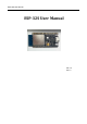
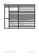


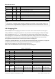
Table Of Contents

ESP-32S User Manual
Shenzhen Ai-Thinker Technology Co., Ltd http://www.ai-thinker.com
Name
No.
Type
Function
NC
32
-
-
IO21
33
I/O
GPIO21, VSPIHD, EMAC_TX_EN
RXD0
34
I/O
GPIO3, U0RXD, CLK_OUT2
TXD0
35
I/O
GPIO1, U0TXD, CLK_OUT3, EMAC_RXD2
IO22
36
I/O
GPIO22, VSPIWP,U0RTS, EMAC_TXD1
IO23
37
I/O
GPIO23, VSPID, HS1_STROBE
GND
38
P
Ground
GND
39
P
Ground
2.3 Strapping Pins
ESP32-D0WDQ6 has five strapping pins. Software can read the value of these five bits from the register
”GPIO_STRAPPING”. During the chip power-on reset, the latches of the strapping pins sample the voltage
level as strapping bits of ”0” or ”1”,and hold these bits until the chip is powered down or shut down.
Each strapping pin is connected with its internal pull-up/pull-down during the chip reset. Consequently, if a
strap-ping pin is unconnected or the connected external circuit is high-impedance, the internal weak
pull-up/pull-down will determine the default input level of the strapping pins.
To change the strapping bit values, users can apply the external pull-down/pull-up resistances, or apply the
host MCU5s GPIOs to control the voltage level of these pins when powering ESP32 on.
After reset, the strapping pins work as the normal functions pins.
Refer to Table 4 for detailed boot modes of configuration by strapping pins.
Table 4: Strapping Pins
Voltage of Internal LDO (VDD_SDIO)
Pin
Default
3.3V
1.8V
MTDI
Pull-down
0
1
Booting Mode
Pin
Default
SPI Flash Boot
Download Boot
GPIO0
Pull-up
1
0
GPIO2
Pull-down
Don’t-care
0
Debugging Log on U0TXD During Booting
Pin
Default
U0TXD Toggling
U0TXD Silent
MTDO
Pull-up
1
0
Timing of SDIO Slave
Pin
Default
Falling-edge Input
Falling-edge Output
Falling-edge Input
Rising-edge Output
Rising-edge Input
Falling-edge Output
Rising-edge Input
Rising-edge Output
MTDO
Pull-up
0
0
1
1
GPIO5
Pull-up
0
1
0
1
Note:
* Pins SCK/CLK,SDO/SD0, SDI/SD1, SHD/SD2, SWP/SD3 and SCS/CMD, namely, GPIO6 to GPIO11 are
connected to the integrated SPI flash integrated on ESP-32S and are not recommended for other uses.