
Data Sheet
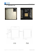
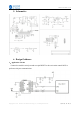
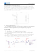
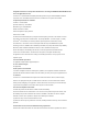
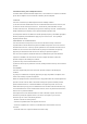
Table Of Contents

Ra-07 datasheet V1.0
Copyright © 2020 Shenzhen Ai-Thinker Technology Co., Ltd All Rights Reserved
第 13 页 共 15 页
2
、
Recommended module package design size
Note: Below is the Ra-07 module package diagram, it is recommended to design the PCB
board according to this diagram, so that the module can work normally on the PCB board; and
pay attention to the design of the pad, the design of the pads on the PCB can not be offset from
the corresponding pads of the module, and the expansion of the PCB pads relative to the
module pads does not affect the use of the module.
3
、
Antenna layout requirements
(
1
)、
Put the module on board edge
,
metal components are prohibited to be placed around the
antenna, and module are requested to far away from the high frequency components.
4
、
Power Supply
(
1
)、
Recommended 3.3 V voltage, Peak:Current over 100mA .
(
2
)、
It is recommended to use the LDO power supply
;
If DC-DC is used, the ripple is
controlled within 30 mV.
(
3
)、
DC-DC power supply circuit is recommended to reserve the position of the dynamic
response capacitor, and the output ripple can be optimized when the load change is large.
(
4
)、
The power interface of 3.3V is suggest to increase ESD components.