Network Camera Model No.: NC233SW View Your World Anywhere……Anytime! Camera Installation on PC and Mac This manual applies to all products. Please read this manual carefully before attempting to install or operate this product.
1.0 Introduction································································································································· ‐ 3 ‐ 2.0 Installation···································································································································‐ 5 ‐ 2.1Pre‐requisites and Initial Connection························································································· ‐ 5 ‐ 2.
5.9.1 System Identity········································································································ ‐ 66 ‐ 5.9.2 User Management·····································································································‐ 66 ‐ 5.9.3 Date & Time············································································································ ‐ 67 ‐ 5.9.
Notice This product may cause interference with other wireless equipment that operate at 2.4GHz ISM band. In the event of interference please turn off one of the devices or move it to a safe distance. Product Assurance This 2.4GHz wireless camera meets wireless frequency security standards and recommended indexes during operation. These standards and indexes are certificated by the academic organization as illustrated in the following paragraphs.
2.0 Installation 2.1Pre-requisites and Initial Connection 1. Mini indoor models, Indoor models, Mini bullets outdoor , bullets outdoor , 3G bullets outdoor models, 3G indoor models, mini spy cameras ,3G spy Camera, DVS. 2. Windows PC or Mac OS or Linux computer with internet browser Computer is only required for initial setup, later the camera can work by itself without any computer present at the camera location 3.
On the box indoor ranges you may want to remove the clear plastic film that is protecting the lens cover. For clearest video be careful not to touch the lens. On indoor models the power light will come on within a few seconds. Later you should also see it blinking red occasionally. This means your camera is ready to use. To get started, you need to know the IP address that your router assigned to the camera. By adding http:// in front of the IP address you get a web link to the camera’s built‐in web server.
If you are familiar with your router’s menus you can log in to your router and see the IP address for the IP network camera in one of your router’s LAN status screens. By the way, in this document we’re using the words “router” and “gateway” interchangeably. 2.2.1 Camera Setup Software Installation for PC For PC users, we supply a program on the CD called Camera Live for PC with Windows7, Windows 8, XP or Vista. This will install utility called Camera Live software on your computer.
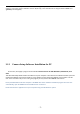
Click Finish to end the installation. You should now find a Camera live icon on your Desktop 2.2.2 Finding your Camera with Camera Live Utility Now you have your camera attached and the software ready, you are ready to find your camera on your network. Double-click the Camera Live icon on your Desktop to launch the Camera Live program. The Camera Live utility should automatically find your camera if it is correctly connected (See image below).
Sometimes the program may take a few minutes to find your camera, so if your camera isn’t displayed, wait a few moments and then click “Search” to search for cameras again. [Search] – Searches your local network for cameras. [Browser] ‐ Select the required camera and click Browser to access the camera via a web browser. [Clean] ‐ Click clean to clean up the searched cameras . [Setup] ‐ Select the required camera and click Setup to configure the network settings for the camera.
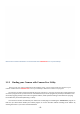
If your camera is online ,manually input the UID or click “Discover” , the connected camera’s UID will show as picture above ,then Click “OK” You will request to fill the user name and password. Finished these steos ,your camera will be shown .Please pay attention to green connect icon on left cornero on picture, “green” means connected , “Red” means you should check again the router and camera to make sure all could connect to internet. Choose your camera and double click ,a video view window will pop up .
You will find you saved pictures and video here ‐ 11 ‐
The second way is click the setup icon on top menu , for more details pleare refer to page 8 . Multiview function is added to this software too . If you want to see several cameras on one screen .
Please Note: To get a best multiview viewing , the Maximum number of camera is 16 . However, there is no limit of adding camera to this window .
2.3 Mac Quickstart This Quickstart section applies to the most common configuration for Mac users: You have an Apple Airport (Extreme or Time Capsule), and your Airport is directly connected to a standard, non‐routing DSL or cable modem. In this section you will be interacting mostly with the Airport Utility.
4. Click on the + (add) button below this box and enter a description for your camera such as “Network camera”, and select “Reserve address by Mac Address”. Enter the MAC address shown on the back of your camera. Be careful about typos. There are numbers from 0‐9 and letters in the range of A‐F only. There is no letter O, just number 0 and letter D . Then select a ip address which is in the Airport DHCP range.
2.3.1 Apple Airport Remote Access Setup In order to access the camera remotely from outside your network, you have to tell your Airport to allow access to the network ports used by the camera.This is called “port setting” and is done with Airport utility as follows: In the Airport Utility version 6.3.1, go to manual setup and select the “Network” icon. 1. Click on the + (add) button below the “port setting”. 2.
2.4 Camera Homepage Regardless of the method you used to find your camera’s IP address, Once you have used the Camera Live Software to find your camera and opened your selected camera or entered the IP address manually into your browser” (with http:// in front) , you will be greeted with the Homepage for your camera (which should look something like the below screenshot depending on your model): [Enter] Lets you view live video transmitted by the camera.
2.5 Live View (using Internet Explorer) When using the camera for the first time on a PC with Internet Explorer, your PC will ask you for permission to install the viewing software (called ActiveX). This ActiveX is needed to decode the H.264 or MPEG4 video stream and control the camera. Click to “OK” this at the top of your screen, then again click on “OK” on the install menu that will pop up in the middle of your screen. If you have a popup blocker like Google Toolbar you will need to disable it.
1)Mute: Click the Mute button to silence the audio stream from the camera. 1) Volume: Slide the slide block horizontally to adjust volume. 1) napshot: Press the Snapshot button to capture a still image of the camera view, these will automatically be saved to the My Documents/ Pictures folder. 2) Video Clip: Press the video record button to enable video recording to your local computer. Once finished press the button again to stop recording. The video clip will be saved by default to the Videos directory.
2.6 Live View (using Firefox, Safari) Upon verification of the username and password, the camera image will begin to load. Adobe Flash Player or QuickTime or your media program may ask you to re‐enter your login username and password at this point. This is common on most systems. Please note: You need to have QuickTime Pro Installed on your system to record videos directly from the web browser if you are using a program other than Internet Explorer.
3.0 Wi-Fi Wireless Most likely your wireless network was set up with a password (also known as wireless key). If you don’t remember it, you can check your router’s wireless setup menu or ask the person who set up your wireless network. Without your password you cannot proceed with your camera’s wireless setup, so you can either continue to use your camera in wired mode or set up a new password in your router.
Click the Search button for the camera to scan for available Wi‐Fi networks to connect to. You may see a whole list of networks in your neighborhood. A new screen will display all the wireless networks found. Select the desired network, and click Apply. The camera will automatically choose the best options for connecting to the network. You then need to enter your Wi‐Fi password.
Please remember that both WPA and WPA2 keys are case sensitive and need to be between 8 and 63 characters. When you have entered the key, click on “Apply”, you’ll get a message about “Wireless setup accepted successfully”, but that only means that the information was stored in the camera. Now you should use the “Test” feature to check if you typed it correctly. If the test reports “Success!” you can remove the network cable and it should work wireless after a short delay.
3.1 Wi-Fi Troubleshooting If the camera does not connect and you’ve already checked the settings mentioned on the previous page, please log in to your router and double check the setting for wireless channel selection. On an Apple airport you would use the Airport Utility. If the “Search” function of the wireless setup page found your Wi‐Fi network it means that the wireless networking hardware is working. If it then doesn’t connect it means that there is a password or IP address related issue.
Some routers like Apple Airport series do not show clearly which one of these settings is being used, so if you have difficulty you should try all 4 possible combinations. On a laptop you typically do not need to specify the exact password type since the laptop will try everything automatically. The camera is picky, it needs to know exactly what type of password you are using and does not try anything other than the exact type that you entered. Remember to “Apply” first, then “Test”.
4.0 Remote Access Setup 4.1 Is the Remote Access Setup already done? If your computer had automatically discovered the camera earlier, this is good news because it means that the “Universal Plug and Play” feature is available on your network and most of the setup may already be done. Your camera would be visible from the internet to anyone who knows the exact IP address and usernames and passwords that you choose.
4.2 UPNP SETUP---Enabling UPnP for Automatic Remote Access Setup Usually it is very simple to enable UPnP. You just need to log in to your router’s setup screen and find the UPnP menu. Then you click on enable, save the setting and restart both the router and the camera (in that order). The camera comes from the factory with the UPnP enabled. You can double check by selecting the UPnP Setup tab under the camera’s Network menu: [UPnP] Enable or disable the UPnP function.
4.3 Overview of Manual IP address setup (without UPnP) In the previous section we showed how to tell if your camera was able to automatically configure itself using your router’s UPnP feature. If UPnP worked, please skip ahead to 4.4.1 DDNS SETUP Step 1‐‐‐Choosing a Name for your Camera on the Internet In this section we provide an overview of the manual IP address setup procedure. You would only need to do this if UPnP is not available on your network, for example if you have an older router.
4.3.1 TCP/IP SETUP --Manual Setup Step 1: Assigning a permanent IP address for your camera on your local network (Without UPnP) On your home network (LAN) all your computers, printers and other network connected devices have an IP address. In every IP address there are 4 groups of digits that can each vary from 1 to 255. For your home network the first 3 numbers are already determined by your router’s address, which is typically something like 192.168.0.1 or 192.168.1.1 or 10.0.
[Obtain an IP address automatically (DHCP)] [Use the following IP address] Select this option when a fixed IP is required. [IP address] Type the IP address of your camera (Required). [Subnet mask] Type the subnet mask (Required). [Default gateway] Type the default gateway (Required). [Primary DNS IP address] Type the IP address of the primary DNS server, if necessary (Optional). [Secondary DNS IP address] Type the IP address of the secondary DNS server, if necessary (Optional).
4.3.2 Manual Setup step 2: Configuring your router to allow access to your camera from the Internet (Without UPnP) If you are not using UPNP or UPNP is disabled on your router, you will need to open a port on your router so that you can access your camera from the internet. If you are unsure if UPNP is working on your camera, visit your camera Settings System page. Under UPNP port forwarding it will be labeled as “Success”, “Failed” or “Disabled”.
4.4 DDNS SETUP 4.4.1 DDNS SETUP Step 1---Choosing a Name for your Camera on the Internet With typical residential internet service your router’s IP address can change from time to time. Looking up the current IP address can be inconvenient, and buying a static IP address is an unnecessary monthly expense. www.dtdns.com and www.dyndns.com are the recommended companies for “Dynamic DNS” service. Also known as DDNS, this is a totally free service that allows your own name to be assigned to your camera.
fee. Now proceed to the next section to make sure your name is updated correctly. 4.4.2 DDNS SETUP 2--Automatic Updating of your Camera’s Internet IP address In the previous step we set up a name for your camera. To make sure that this hostname always corresponds to the correct IP address for your camera we have to make sure it is updated automatically when there is a change. Dynamic DNS (DDNS) is simply a way of using a static hostname to connect to a dynamic IP address.
If it says “Updating” or Unavailable” you should double check your account settings. No‐IP.com uses your complete email address as user name, and the password required in this menu is the one you created during No‐IP account setup. If successful the camera will show you the complete external URL for your reference. The external address using DDNS is made up of two parts – your DDNS account address and the port you opened via UPnP or manually. For example: DDNS Host name account: http://yourname.dtdns.
5.0 Camera Settings 5.1 Login Password Modification You can now view your camera live, but this is only on your local network, so you can now refine and customize the settings of the camera. To continue with camera customization, access your camera’s Settings page by clicking on the “Settings” word from your Live View, or click on the word “Settings” from the Camera Homepage.
‐ 36 ‐
5.2 Quick Setup with the Wizard To make the setup process slightly quicker for users, we have created a Setup Wizard which takes you through common options to getting your camera setup wirelessly and with your custom settings. Within the Settings screen, click on “Wizard” in the Header Menu. The Wizard will launch in a new window. Follow the simple instructions on the screen and enter the required details, clicking next to proceed through each step.
5.3 System Page From within the Settings menu, clicking on “System” at the top right will list the system information of your camera. This screen is one of the most useful in the camera Settings. This screen lists information you may need if you want connect to your camera from other systems. It’s a great way to check if your camera has all the details needed to operate correctly. Firmware Version – Your current firmware version. Check the .com website or contact our technical support: support@ .
5.4 Reboot Click Reboot in the Header Menu to access the Camera Reboot page to restart the camera. Rebooting the camera will retain all the settings and configurations. A reboot is normally necessary when you insert a microSD card into the camera. 5.5 Camera Menu 5.5.1 Camera Setup The Camera menu is located on the right of the Settings screen. When you click on the word “Camera”, a sub‐menu of camera setup options will be displayed. For most users, many of these settings can be left as default.
Click Apply to confirm your setting. 5.5.2 Stream Setup Click on Stream Setup under the Camera Menu to change the streaming settings for your camera. This is useful if you require a certain size of video stream, a certain quality, or different streams for different devices (such as laptop or mobile phone). Default settings will normally suffice for most users. There are a number of video streams available. You can configure settings for the primary and an optional secondary video stream.
Stream Setting Options [Present] There are five pre‐programmed stream profiles for quick set‐up. Please choose the one according to your bandwidth. [Image size] Image resolutions available are as follows: 480P Model: 640 x 480(VGA), 320 x 240(QVGA), 160 x 120 (QQVGA). The mobile stream has a fixed image size of 176x144. HD 720 Model: 1280x720 (HD720p), 768x432, 512x288, 256x144). The mobile stream has a fixed image size of 176x144.
5.5.3 Image Setup [Brightness] make the image brighter or darker by a specified amount. When increasing brightness, you may find that you lose some contrast on the brightest details in the image while the rest of the image has the same contrast as before. [Contrast] Contrast is defined as the separation between the darkest and brightest areas of the image. Increase contrast and you increase the separation between dark and bright, making shadows darker and highlights brighter.
5.5.4 OSD Setup Click on OSD Setup under the Camera Menu to change the on‐screen display parameters of the camera. On Screen Display Setting Options [OSD] Enable or Disable the On Screen Display. OSD Options [Display date and time] Set the OSD to display the Date and Time of the camera.
5.5.5 Night Vision Settings At night, with the infra‐red lights, the cameras simply show reflected light. If the camera is pointed at empty space (not pointed at trees, grass, or other objects), the night time picture will be entirely black. The infra‐red lights seem to project out roughly 50 feet ‐ of course at that distance at night it will be difficult to pick out many details about the object that is recorded.
With LED and Moonlight mode “OFF” With LED and Moonlight mode ON or Auto Please note: If you are using the cameras to look through a window, you should set the night vision mode to turn off the IR LEDs instead turn on the automatic moonlight mode. Otherwise the IR LEDs would reflect off the window glass and the glare would make everything almost invisible. 4. “IR Cut Filter control”‐‐ IR is present naturally in day light, this can cause discolouration of images where the greens can look purplish.
5.6 Network Menu The Network menu is located on the right of the Settings screen. When you click on the word “Network”, a sub‐menu of network setup options will be displayed. Skip the wireless setup chapter, please check page 18 to 21. Skip the TCP/IP setup chapter, please check page 25 to 26. Skip the DDNS setup chapter, please check page 28 to 30. Skip the UPnP setup chapter, please check page 23. Skip the P2P setup chapter, please check QuickGuide. 5.7 STORAGE 5.7.
5.7.2 MicroSD Card Information and Installation Adding a Micro SD to your camera will allow you to record footage and motion alerts direct to memory card for future review. Please note: It is advised to insert the microSD card before any other setup begins as the card will not be recognized if inserted once the camera is turned on. Every time the card is re‐inserted, you will need to turn the power off and then on again for the card to be recognized.
5.7.3 MicroSD card installation The MicroSD card is not included in packages. The slot for the Micro SD card is at the right side of the indoor cameras and behind the lens cover on outdoor cameras. (See diagram below). The card can only be inserted into the camera with the golden pins of the microSD card facing the front of the camera. The SD card should not be forced into the SD card slot as this may damage the camera.
‐ 49 ‐
To access the Micro SD card slot on the outdoor camera, please bring the camera indoor (in an area of low humidity), then unscrew the entire front part of the camera. It is easiest to do it if you take the sunshield off first. The Micro SD card slot is right under the reset button show below Please be very careful not to touch the lens. The Micro SD slides into the slot and there is a positive “click” when it is locked in place. If it doesn’t want to go in effortless it is probably upside down.
5.7.4 NAS STORAGE SETUP [NAS remote path] This is the address & path where to save the files on NAS Drive (up to a maximum of 2 directory levels). [Authorization1] Select whether authentication is required by the NAS Drive. [User name] & [Password] Type the user name and password of the NAS Drive. This field is required if your NAS Drive requires authentication. Click Apply to confirm your setting. Please note : After the setting on “Storage“ and Micro‐SD card or NAS status is ready.
[All] Enables you to view and delete all the files recorded. [Snapshot on Alarm] Enables you to view and delete snapshots which were recorded upon motion detection [Snapshot at Interval] Enables you to view and delete all the snapshots which were recorded on periodicalbasis [Record on Alarm] Enable you to view and delete all the videos which were recorded upon motion detection [Continuous Record] Enables you to view and delete all the videos recorded according to the continuous record schedule.
Login to the camera, under Settings>Storage>Format SD card Note: Before the SD card is formatted the Format SD card page will display status as "Not Ready". The SD card format can take a few minutes depending on the size of the SD card. A reboot is normally necessary when you insert a microSD card into the camera and after formatting the microSD card with the camera’s format tool. 5.8 TASK 5.8.
The camera refers to motion detection as an “alarm”. You can select what you want the camera to do once the motion is detected. In general, motion detection works by comparing the current video frame with the averages of the previous video frames. Any difference is considered to be motion, and the sensitivity adjustment can be used to make the camera more aware or less aware of small amounts of motion.
visit http://www.pcpitstop.com/testax.asp To reduce the chance of false alarms you would increase the threshold (move threshold slider to right) or decrease sensitivity (move sensitivity slider to left) . 5.8.2 Motion Detection using other browsers(Firefox, Chrome, Safari) [Window] Check this box to enable the window. [Threshold] Determines at what point the alarm is triggered. A lower threshold means less motion is needed to trigger the alarm.
By default, the schedule is set to be “active” at all times “always”. However you can set the schedule not to trigger alarms at certain times (useful for instance if you don’t want alarms to go off while your office is open from 9am until 5.30pm). You can set up to 4 schedules, and you can use these to send alarms to different places – such as emails, FTP or SD card. Schedule Setup Options [Schedule ID] Select the ID, you can save up to 4 schedules and use them for different purposes. [No.
[Enable] Enable task. [Schedule] Option to choose always or set a particular schedule. Check Schedule setup to select the right schedule ID for your task. [Task] Task function. Click on the task to login the task setting screen below. Click Apply to confirm your setting 5.8.4.1 Email Alarm Sending/Email Periodic Sending For automatic emailing you will need both an outgoing email server and one or more email receiving addresses.
Note: Gmail requires that you go to your account settings on Gmail.com and enable the POP feature (Post Office Protocol). If your Gmail account does not have POP enabled, the camera will not be able to send email. [Enable] Enable task. [Schedule] Option to choose always or set a particular schedule. Check Schedule setup to select the right schedule ID for your task. [Task] Task function. Click on the task to login the task setting screen below. Click Apply to confirm your setting 1.
2. Snapshot Duration‐‐ The number of seconds that the camera should keep sending emails with attached image after motion stops. 3. Snapshot Frame Rate‐‐ The number of frames per seconds that the camera should keep sending images at when an alarm is triggered. If “Snapshot duration” had a value of 4 and “snapshot frame rate” had a value of 2, you would be getting 2 images each second for 4 seconds in a row, meaning 8 pictures total for each motion detection event. 4.
Period Interval‐‐ Time interval between snapshots. It allows you to designate a time (in seconds or minutes or hours) during which new emails are suppressed. For example, if you want to avoid a flood of emails, you could set this time to 60 minutes so that you wouldn’t get any new emails for 1 hour. Some email server settings to use your camera with popular email providers: gmail.com SMTP server name: smtp.gmail.com SMTP server port: 465 Secure SSL: Yes Authentication: Yes Username: YourUserName@gmail.
If you prefer, you can have the pictures uploaded to an FTP server instead of an email address. There are many choices for FTP servers. For example, you could enable the built‐in FTP server function on one of your computers or download free FTP server software such as FileZilla server. Another possibility is to use an online account with FTP access, which is sometimes even available for free with a limited amount of storage.
“Authentication” should be set to “Yes”. [FTP server port] The port number of the FTP server (default is 21). [Remote path] Input the file directory. It is an optional setting to specify a folder on the FTP server. If you decide to use this feature, you have to make sure that the folder exists on the FTP server with the exact same spelling. [Authentication] Select whether authentication is required by the FTP server. Choose “No” for anonymous access. [User name] Type your FTP user name.
5.8.4.5 Record to Storage on Alarm/ Record to Storage Continuously [Enable] Enable task. [Schedule] Option to choose always or set a particular schedule. Check Schedule setup to select the right schedule ID for your task. [Task] Task function. Click on the task to login the task setting screen below. Click Apply to confirm your setting 1. [Record from]‐‐ Select the stream from which it should record. It can be “Primary stream” , “Secondary stream” and “ Mobile Stream” .
[Enable] Enable task. [Schedule] Option to choose always or set a particular schedule. Check Schedule setup to select the right schedule ID for your task. [Task] Task function. Click on the task to login the task setting screen below. Click Apply to confirm your setting [FTP server name] Type the name or IP address of the FTP server. At a minimum you need the IP address (FTP server name) for your FTP server.
[Enable] Enable task. [Schedule] Option to choose always or set a particular schedule. Check Schedule setup to select the right schedule ID for your task. [Task] Task function. Click on the task to login the task setting screen below. Click Apply to confirm your setting [Post time]‐‐The number of seconds that the camera should keep alarm message sending after motion stops. If there is any motion within this time the camera will keep sending alarms until there is no motion for the duration of this parameter.
5.9.1 System Identity [System Name] Type a name to easily identify the camera. [System Contact] Type the contact name of the administrator of the camera. This is useful in large organizations. [System Location] Type the location of the camera. This is useful when using a multi‐camera viewer program. Tip: The information you fill in can be displayed on the camera. It can help to distinguish different cameras on the network. 5.9.2 User Management Allows you to add or remove users who can view your camera.
[Add] Up to 64 users (including the admin) can be created. Adding users: Click Add on the Camera User List page, then fill in a username and password (twice) and then click Add. To edit a user’s password: Click on the user name then enter the new password for that user twice and click Save. To delete a user: Click on the user name then click Delete. Note: A maximum of 16 users are allowed to access the camera simultaneously.
[Current device time] Internal time of the camera. [Proposed device time] PC system time. On clicking Apply the internal time of the camera will be changed to this time. [Select to change the time zone for the device location] Choose your time zone. [Daylight saving time] tick the box to enable daylight saving time. [Date and Time format] Select the format of the date and time. [Auto time setting (SNTP)] Enable or disable the auto time setting to update to the server below.
[Reset] Click Reset to initialize the camera to default factory settings. All users and settings will be lost, requiring you to reconfigure the camera. [Backup] Click Backup to back‐up the current configuration of the camera for future reference. Once you have your camera setup as you require, this is recommended. To restore a backup file: [Browse...] Click Browse... to search for a backup configuration you wish to upload to the camera, then click Restore.
5.9.6 Firmware Upgrade From time to time a new firmware may be released for your model of camera. To check for updates, consult with our technical support before firmware upgrade. Once you have downloaded the latest firmware, store it in a place that is easily to get to. The firmware is in a ZIP file, which is a compressed file format.
Wait 3‐5 minute till the warning message “ Caution ! Upgrading Firmware! Please don’t turn off power or reset the camera till firmware upgrade successfully” displayed. Till warming message above displayed, then Wait 2‐3 minutes again till the message. After the upgrade completes, you will be prompted “ Firmware upgrade successfully, reboot now ?” to reboot the camera, then click “reboot”, after this your latest firmware will be recorded.
5.9.7 Resetting the Camera back to Factory Settings Note: Do not turn off the power during the Restore function since this might corrupt the camera’s firmware. If you ever forget your admin password or have any other reason to reset the camera to its factory settings, please use the following procedure: 1. Make sure the camera is powered up 2. For indoor cameras insert the tip of a paper clip in the hole at the side of the camera to press the reset switch. You’ll feel the click when the switch engages.
While we don’t recommend this, it is still possible to configure the camera without an initial wired connection using the following procedure: 1. Temporarily rename your Wi‐Fi network name (SSID) to: wirelessnc, and turn off all wireless security, i.e. no passwords and no MAC filtering. It is important to have the SSID all lower case and without extra spaces. Then connect to this Wi‐Fi network with your laptop. 2.
For the next camera, you call the first application Cam2HTTP and use public TCP port 8151 while still using “map to host” port 80. The second application would be Cam2RTP with UDP ports 30002‐30003 and map‐to‐host port 30002. Appendix C: Manually entering TCP/IP Settings for a Camera In most cases, this is not required as the router will assign the correct settings to the camera.
1. Enter a unique name for the camera, the location (optional) and leave the default port number as 80. “Obtain an IP address automatically” and “Obtain DNS server address automatically” are selected by default, if you are confident enough to enter your own settings, you can do so by selecting “Use the following IP address” and follow the guidelines on the next page. 2. To obtain the IP addresses specific to your network, click “Start” then “Run” and type “cmd” in the text box and click “Ok”.
Appendix D: Enabling Active X in Internet Explorer Your browser must have Active X enabled to view the camera in Internet Explorer. To activate this, do the following: 1) Open a new Internet Explorer window. 2) From the menu bar, select Tools, and then select Internet options… 3) From the Internet Options window, select the Security tab. 4) Click on the Custom Level… button. 5) Scroll down to the section labelled ActiveX controls and plug‐ins.
unresponsive. If the firmware update failed, and your cameras BIOS loader has become corrupted, your cameras LED will be flashing green when turned on. There is a procedure you can try yourself, however it is quite advanced, so should only be attempted by those with a solid understanding of TCP/IP and running commands from the DOS command prompt. Procedure: 1. Download the correct new firmware for your camera from our technical support and save this to your hard disk. 2.
Do not turn the power on at this time. You must then assign your computer an IP address so it can talk easily to the camera. On a PC: 1. Open the Control Panel and double click on “Network Connections” then right click on your “Local Area Network” connection, and click Properties. Be sure to select the Network icon that corresponds to where you have plugged the camera in to – so this would not be listed as a Wireless, Wi‐Fi or Bluetooth Network. 2. Select “Internet Protocol (TCP/IP)” then click Properties.
activates the digital output to trigger a burglar system. With a Maximum voltage of 60V, this output has an open collector NPN Darlington transistor with the emitter connected to the GND pin. If used with an external relay a reverse polarity diode must be connected in parallel with the relay coil to protect against voltage transients. You would need to select a relay that uses less than 0.4A at 12V, and the relay and the diode would connect pins 3 and 4.
green and the camera is inaccessible Motion Detection triggers unexpectedly What do the changes to the LED light mean? Please contact your place of purchase or TriVision Technical Support 1. Motion detection is based on changes in pixel in the image. This means that if there are sudden changes in the lighting, motion detection may be triggered mistakenly. Lower the sensitivity setting to avoid problems. Amber ‐ Steady for connection to a 10/100 M bit/s network. Amber ‐ Flashes for network activity.
FCC STATEMENT : This device complies with Part 15 of the FCC Rules. Operation is subject to the following two conditions: (1) This device may not cause harmful interference, and (2) This device must accept any interference received, including interference that may cause undesired operation. Warning: Changes or modifications not expressly approved by the party responsible for compliance could void the user's authority to operate the equipment.