
User's Manual
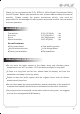

RECEIVER
www.art-tech.com
8
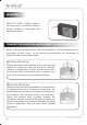
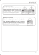
With E-FLY ER61-2.4GHz receiver,
the max range is 1000 feet (350m) in
the air, suitable for small park flyer
type model plane
TRANSMITTER OPERATION AND MOVEMENT OF EACH SERVO
Before making any adjustments, learn the operation of the transmitter and the
movement of each servo. (In the following descriptions, the transmitter is
assumed to be in the standby state.)
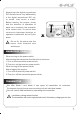
AILERON OPERATION
When the aileron stick is moved to the right, the right
aileron is raised and the left aileron is lowered,
relative to the direction of flight, and the plane turns
to the right. When the aileron stick is moved to the
left, the ailerons move in the opposite direction.
ELEVATOR OPERATION
When the elevator stick is pulled back, the tail elevator
is raised and the tail of the plane is forced down, the
airflow applied to the wings is changed, the lifting force
is increased, and the plane climbs (UP operation).
When the elevator stick is pushed forward, the
elevator is lowered, the tail of the plane is forced up,
the air flow applied to the wings is changed, the lifting
force is decreased, and the plane dives (DOWN
operation).
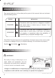
CERTIFICATION
We offer 35Mhz, 41Mhz and 72Mhz transmitter. The
40Mhz or 41Mhz transmitter has CE certification and the 72Mhz transmitter has FCC
certification.
36Mhz, 40Mhz, 35Mhz, 36Mhz,
CERTIFICATION
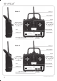
1.
2.
3.
4.
5.
6.
Pitch
Undercarriage
Rudder
Throttle
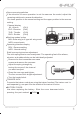
Servos Black Red White
Elevator
Aileron
Operating voltage: 4.5V-6.5V
Current drain: 10mA
Number of channels: 6CH
System: FM(PPM) Single conversion
Sensitivity: 1V
Weight: 15g
Size(L x W x H): 47mm x 24mm x 12mm
Range(Height): 500m
Range(Distance): 400m
Adjacent channel rejection: -65dBm 16kHz
Available 35MHz receiver is compatible with JR transmitter, 40 Mhz
receiver is compatible with JR transmitter 72 Mhz receiver is compatible
Futaba transmitter.
Caution: When you plug the servo cable into the receiver, the black wire of
the servo cable should be nearest to the outside of the receiver box.
SERVO
We offer 6gram, 9gram and 17gram servos for selection. We offer 3 servos
in one package.
CRYSTAL
The crystal is located on the side of the receiver.
Output / battery connector
Aileron servo (Ch1) Elevator servo (Ch2)
Throttle servo (Ch3) Rudder servo (Ch4)
MANUAL FOR BRUSHED ESC
Features:
Can control the motor run deasil and anti-clockwise.
Full proportional liner.
Auto cut-off for low voltage.
Signal loss protection: while no signal received, the ESC will auto cut-off
In order not to hurt anyone due to out of control.
Assembling:
1.Turn the transmitter on and push the throttle into minimum.
2.Plug the signal wire to the receiver and make sure all is correct.
3.Connect the battery and ESC and pay attention to the polarity, or that can
cause the damage to ESC. If there is the sound like “ beep” , that means
everything is ok. If not, please check whether is ok, like the wire connection,
battery and the position of throttle.
4.After the Beep sound is over, you can start the motor by moving the throttle.
5.If the motor runs in the opposite direction as what you want, you can change
the connector of motor.
6.The connections between motor and ESC should be well protected, or that can
cause the damage to ESC
7.Please use this ESC under the working currency.
8.When the battery voltage is under the safety level or there is signal received,
ESC will auto cut off the supply for motor.
Signal connector for receiver:
white:Signal wire
Red: positive
Black: negative
Battery connector
Connector
for motor
Specifications:
30A
Input voltage:5V~14.4V
Output currency:30A/50A (Max)
BEC:5V/1A
Auto cut-off voltage:5V
Starting: throttle in min
(Starting point:1.0-1.5ms)
Dimension:21 x 32 x 10mm
Weight:15g