
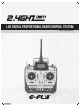
User's Manual
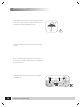
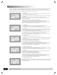
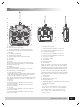
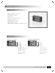

A:Antenna
B:LCD(Liquid Crystal Display)
1)To indicate the battery voltage of transmitter
2)To show the situation of channels whether it is
reversed
3)To show the flying time
4)To indicate flying mode
C:Tiny Mix 1
D:Tiny Mix 2
E:Switch 1
This switch is for Ch5 tha t can b e use d fo r aeria l
camera, collapsible landing gear and shift between
gyro mode and gain, etc.
F:Switch 2
G:Flying Mode Switch
When the lock switch is on ADJUST,it is can be
adjusted to A/V/H/C Flying Mode
H:LED Indicator for Power
I:Red LED Indicator for low Voltage: When battery is
under 8.5V,t he L ED w ill h ave a f lash a larm;th e L CD
will cut off when voltage is under 7.6V。
Note: When red LED flashes or nothing shows on LCD,
pls change the battery in orde r t o avoi d flyin g o ut
of control.
J:Joystick
1)If the transmitter is Model 1,CH1 is for aileron
and CH3 for throttle.
2)If the transmitter is Model 2,CH1 is for aileron
and CH2 for Rudder
K:Joystick
1)If the transmitter is Model 1,CH2 is for elevator
and CH4 for rudder.
2)If the transmitter is Model 2,CH3 is for throttle
and CH4 for rudder.
L:Tiny Mix for Channels
1)If the transmitter is Mode 1,it is for Ch3
2)If the transmitter is Mode 2,it is for Ch1
M:Tiny Mix for Channels
1)If the transmitter is Mode 1,it is for Ch1
2)If the transmitter is Mode 2,it is for Ch3
N:Tiny mix For Aileron
O:Tiny mix for rudder
P:Flying Ring
Q:Switch for Power
R:Lock Switch
When the switc h is on Lo ck stat us , all are lock ed,
including switch fo r flying mode, tin y mix1,an d tin y
mix2 When the switch is on adjus t status , a ll ca n b e
changed,including flying modet,i ny m ix1an d tin ymi x2
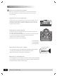
S:CH1, CH2, CH3, CH4, CH6 Reversed Switch
For changing the turning of servo, up for reversed and
down for normal. REV:Reversed NOR:Normal
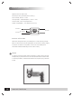
T:Steel Handle
U:TX Crystal
V:Battery bay for transmitter
W:Plug for Simulator
X:Rechargeable plug ( Note:Onl y 9.6V Nih e batter y
pac k can be recharged )
Y:Witch 3
The switch is t o chang e th e turnin g rang e of
servo(s 10 0% / 70% )for C H1, CH2, CH4.W hen
it is 0, im t eans th e tu rning ra nge of servos is
1 00%. W hen i tis 1, it m eans th e tu rning ra nge
of servos is 70%.
Transmitter particular introduce
D
F
H
J
L
N
P
R
A
B
C
E
G
I
K
M
O
Q
S
Y
5)To indicate the status of lock and unlock
X
U
T
V
W
www.art-tech.com
07