
User's Manual

www.art-tech.com
06
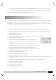
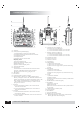
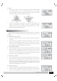
Transmitter particular introduce
A:Antenna
B:LCD(Liquid Crystal Display)
1)display battery voltage of transmitter
2)display whether the channels are reversed
3)display flying time
4)display menus
5) Display lock or unlock state
Display area
1)function display area
2)channels direction display area
3)data display area
4)option number display area
C:Throttle hold switch
D:Ch5 switch
This switch is for Ch5 that can be used for aerial
camera, collapsible landing gear and shift
between gyro mode and gyro gain, etc.
E:3D switch
F:D/R switch
G:Indicator LED for Power voltage
H:Red Indicator LED for low voltage alarm: When
battery voltage is under 8.5V, the LED will flash and
alarm; the LCD will cut off when voltage is under 7.6V。
Note: When red LED flashes or nothing shows on
LCD,
please change the battery in order to avoid
flying out of control.
I:Joystick
1)If the transmitter is Mode 1,CH1 is for aileron
and CH3 for throttle.
2)If the transmitter is Model 2,CH1 is for aileron
and CH2 for Rudder
J:Joystick
1)If the transmitter is Model 1,CH2 is for elevator
and CH4 for rudder.
2)If the transmitter is Model 2,CH3 is for throttle and
CH4 for rudder.
K:Throttle trim lever (Mode 1)
Elevator trim lever (Mode 2)
1)If the transmitter is Mode 1,it is for Ch3
2)If the transmitter is Mode 2,it is for Ch1
L:Elevator trim lever (Mode 1)
Throttle trim lever (Mode 2)
1)If the transmitter is Mode 1,it is for Ch1
2)If the transmitter is Mode 2,it is for Ch3
M:Rudder trim lever
N:Aileron trim lever
O:Switch for Power
P:Flying Ring
Q:Menu Button
1) Enter into main menu
2) Enter into next main menu
3) Enter into time page menu (release after long
press)
R:Sub Button
1) Enter into sub menu
2) Enter into next sub menu
3) Enter into time page menu (release after long
press)
S:Y/UP
1) Selection validate
2) Data increase
3) Normal channel direction selects (release after
long press)
T:RIGHT Button, selection(right)
U:N /DOWN
1) Selection cancels
2) Data decrease
3) Reverse channel direction select (release after
long press)
V:LEFT Button, selection(left)
W:Steel Handle
X:Bind Button
Y:Plug for Simulator
Z:Battery bay for transmitter
A1:Rechargeable plug ( Note: Only 9.6V Ni-MH
battery pack can be recharged )
X
W
Z
Y
A1
LCD DIGITAL PROPORTIONAL RADIO CONTROL SYSTEM
MENU
LEFT
RIGHT
Y/UP
N/DOWN
SUB
E
G
J
L
N
P
V
A
B
C
D
H
I
K
M
O
F
S
T
U
Q
R
ETC62-2.4GHz