
User's Manual


39285 English I/B ver. 11182A-1
11182A-1
8
OWNER’S MANUAL #
39285
ver.
11182A-1
Page: 8 ENGLISH VERSION
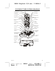
Volume Control Down Button – Press to
decrease the volume level of the base unit
speaker.
Volume Control UP Button – Press to
increase the volume level of the base unit
speaker.
Redial/Pause (RE/PA) Button – (Redial) –
Press to redial the last number you called in
the speakerphone mode. (Pause) – Press to
insert a pause while dialing. (you will need
the (re/pa) button to dial numbers which use
an alternative long distance access code.
Ringer ON Button – Press to enable the
base unit ringer.
Tone/Pulse Switch - For Charging the
Battery Pack inside the handset. We
recommend cleaning the Charge Terminals
periodically with a damp cloth.
Power In Connection Jack
Telephone Line Connection Jack
INSTALLATION
CAUTION:
USE ONLY THE NICKEL
CADMIUM (Ni-Cd) BATTERY TYPE INCLUDED
WITH THIS UNIT. USE OF OTHER BATTERY
TYPES MAY CAUSE INJURIES OR DAMAGE.
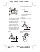
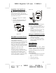
Battery Installation
1. Remove the battery compartment cover
of the handset by sliding it down.
2. Connect the Ni-Cd battery pack plug
along the slot into the handset’s battery
connector as shown below.
(Figure 1)
3. Insert the Ni-Cd battery pack into the
battery compartment.
4. Replace the battery compartment
cover by sliding it up towards the
handset.
NOTE: Use the type and size of Ni-Cd
battery pack, 3.6V, 600mA. It is
recommended that the Ni-Cd battery pack
should be fully charged overnight prior to
initial use.
Belt Clip Installation
With the back of handset facing up, insert
one side of the belt clip hook into the
matching slots at the top side of the
handset as shown in Figure 2. Slide the
other hook until it locks into place from
the opposite side of the handset.
(Figure 2)
Wall Mounting (With a standard AT&T
or GTE modular wall jack)
You may choose to install the Telephone
base unit onto a wall.
Wall Mounting (Standard Wall Jack)
1. Connect the short telephone line cord
to the telephone line jack on the rear
of the base unit.
2. Insert the free end of the short line
cord through the hole of the mounting
bracket.
3. Insert the hooks of the mounting
bracket into the matching slots on the
back of the unit as shown in Figure 3.