User Manual LCD Monitor Model: C16S SERIAL Rev.
Contents 1. 2. 3. 4. 5. 6. 7. 8. 9. 10 Application................................................................................. 1 Declarations................................................................................ 1 Installation................................................................................ 6 Start-up.................................................................................... 6 4.1 Connecting the power and signal cables .............................................
1. Application This high-resolution color display with touch screen use is specifically designed to meet the rigorous performance standards needed for diagnostic, interventional radiology, and other medical applications. To guarantee image integrity, features include accurate signal conversion and a wide range of interfacing options. Compact design -Low weight and small size with improved performance make the color flat panel display HL1916S SERIAL preferable to conventional CRT monitors.
Appliance coupler or separable plug of is used as isolation means to isolate the equipment from mains supply. Accessory equipment connected to the analog and digital interfaces must be certified according to the respective IEC/EN standards (e.g.IEC/EN950 for data processing equipment and IEC/EN 60601-1 for medical equipment). Furthermore all configurations shall comply with the valid version of the System standard IEC/EN 60601-1-1.
Do not place any objects on top of the units Penetrating liquids may result in a fire or electric shock. Connection No contact to a patient must occur when handling the cables. Do not hurt yourself, when moving the display The display can be tilted backwards and forwards. Please, pay attention not to hurt yourself, when moving the display. Fingers or small objects may get stuck at the bottom of the display.
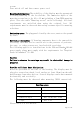
screws. Turn switch off and then remove power cord. Mounting information: The stability of the display must be guaranteed following mounting of the foot/holder. The immersion depth of the mounting screws has to be 10 to 12 mm including a 3 mm VESA mounting plate. (See also table "Mounting screws" on the following). All these requirements are satisfied when using the original foot. All requirements must be observed when using customer-specific mounting solutions.
The permissible ambient temperature range (5 °C ... 35 °C) must not be violated. Do not subject device to unnecessary shocks. Take care when transporting! Use the original packaging! The panel in particular should be protected against shocks. When touching the panel surface, the mechanical contact or an electrical discharge may cause a brief disturbance in the picture quality. Care of unit / cleaning agents − The front panel is extremely sensitive to mechanical damage. Avoid all scratches, knocks etc.
3. Installation Provide adequate ventilation Ventilation slots are located on the rear of the housing. Ambient temperature The permissible ambient temperature range must not be violated. Minimize reflections The display should be positioned so that reflections of lights, windows, furniture with shiny surfaces or light-colored walls do not appear on the screen. Minimize mirroring In order to reduce mirroring on the unit, ceiling lighting or reflected light (no dazzling) should be used.
If the display is to be used in a sequence of several displays, or if it is not exactly known whether the graphics card standard can be output by the display, refer to Section 5.1 "Connection of the flat panel display". In order to start the unit properly, the following steps should be carried out in the given sequence. 4.1 Connecting the power and signal cables Warning The display can be tilted backwards and forwards. Please, pay attention not to hurt yourself, when moving the display.
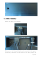
4.1.2 Cable (attaching) Connect the cables to the display. VGA connector: the flat panel display can be connected to the computer system using a VGA Cable on D-sub connection for analog signal.
display is adapted using an OSD menu. DVI-D connection: The connection to the computer can also be made via the digital single link. The picture quality, noise immunity and radiated interference of the complete system depend on the cable quality and length. DP connection: The connection to the computer can also be made via the DisplayPort connection. The picture quality, noise immunity and radiated interference of the complete system depend on the cable quality and length.
Button of stand base Note: the stand base is optional. 4.1.4 Mounting Use Remove the stand base according to the contrary way in 4.1.3. Fix the mount by mounting screws (see page 6 table Mounting Screws for details).
4.2 Switching on the display Switch on the flat panel display using the power switch. The operation LED lights up (color: green, provided the timing has been recognized – please refer to section 7 "Fault diagnostics"). 4.3 Adjusting the image geometry The display automatically recognizes the used standard, and set-up values for each standard are preprogrammed. However, depending on the graphics card used, it may still be necessary to align and size the picture for the selected standard (see Section 6.
5. Connections 5.1 Connecting the flat panel display Note All screening precautions contained in the corresponding EMC guidelines must be observed. If these guidelines are not observed, interference signals could penetrate the monitor. Information on cable installation Only screened cables are permitted for the signal connections. All connectors should be of screw or locking types (as far as possible). Signal and power cables must not be routed in the same duct.
to the computer for firmware updating and monitor test. 5.4 Analog and digital inputs (DVI,VGA,DP) DVI socket With DVI digital signal through DVI cable. VGA socket Use VGA cable for VGA input. DP socket With DP digital signal through DP cable. 5.5 Power supply connection Note Device fuses can not be exchanged outside of the repair centers. The display power supply is connected using an appliance plug.
Figure 4 Pin USB-B connector Signal 1 VBUS 2 D- 3 D+ 4 GND 6. Adjustments 6.1 Picture adjustment This section describes the settings for operation of the flat panel display with a video source. The most important settings are: Adjusting the graphics memory of the video source As with all monitors, the flat panel display also has certain limits, e.g. maximum resolution and vertical frequency. The graphics adapter must be set when using the flat panel display such that the limits are observed.
picture source, cable length and video mode (e.g. VGA, SVGA, XGA) this conversion may cause certain deviations which cannot be corrected fully automatically by the flat panel display. A manual fine adjustment is therefore necessary during which the flat panel display (or, more precisely, the video digitizer) is matched to the respective video source. The fine adjustment comprises e.g. setting the horizontal/vertical picture position and the picture sharpness.
of 1280 x 1024 pixels (settings for graphics card in the PC). When adjusting the picture position and size, ensure that the picture appears exactly on the active surface of the display and that it is not offset by even one pixel. For example, if the horizontal position is offset by one step to the right, the right-hand edge of the picture will disappear, and a black pixel column will appear at the left-hand edge. And similarly for an offset to the left, top or bottom.
6.3.2 Key functions without active OSD menu Key Action Menu Activate OSD Up Define VGA port Down Select DVI-D,DP, VGA input source Note: While there is no sync in VGA input, there is instruction on the OSD to indicate that how to define the analog input as VGA input. Press and hold the ‘UP’ key for about 2 seconds, the monitor will change the analog input between VGA. The ‘Down’ key function is used to select input source and is enabled only when OSD menu is locked.
6.3.6 Description of the menus Main Menu Performance Display Settings Function Brightness Adjustment range 0…100 Contrast 0…100 Backlight 0…100 Color Color1 Color2 Color3 User R G B Gain R G B Bias 0…255 H Position (Analog only) V Position (Analog only) Description Set brightness. Adapting the image quality of darker picture areas. The center point is in 50 position. Note: The brightness settings are already optimized for digital signals.
Input Source Auto Adjust (Analog only) DVI-D DP VGA Auto-Color ON / OFF Auto-Configure ON / OFF Execute OSD Settings Information Service Level 2 digital signals which is lower than 1280 x 1024 can be adjusted. Analog signals can be adjusted in all supported resolution. Negative figure is adjusted to get softer image and positive figure is adjusted to get sharper image. The user should individually adjust the filter depending on the application. Select the active input source priority.
Exit Check box for save or reject the changes when Quit OSD menu . Reject changes Accept changes Quit OSD 7.
Picture diagonal 19" or 48 cm Native resolution 1280 x 1024 (full-screen format) Pixel organization 3 vertical sub pixels Pixel pitch 0.294 mm x 0.294 mm Contrast ratio Typically 900:1 Horizontal angle viewing Typically ± 85° (CR≥10) Vertical viewing angle Typically ± 80° (CR≥10) Backlight LED Brightness Max backlight: brightness MIN 260 cd/m² .
8.4 Inputs/outputs 8.4.1 Analog signal input VGA input Via VGA socket, single link 8.4.2 Digital signal input DVI-D input Via DVI socket , single link DP input Via DP socket DDC Via DVI 8.4.3 Serial interface RS232 Via RJ11 connector 8.4.4 Timing Input Item Frequency Analog VGA SPEC Horizontal: 31 ~ 82kHz Vertical: 56 ~ 75Hz Pixel clock 25—140 MHz Video Bandwidth ≥ 165M Hz Video Input Analog 0.
DVI-Digital DVI Single link Digital Display TMDS: 600mV for each differential line Input Impedance: 50 ohm DVI EDID datum EDID via DVI Display Port 1.1 Receiver 4 main Lanes Port I2C bus Display Port: 600mV for each differential line Impedance: 100 ohm per differential pair DP EDID datum EDID via AUX channel 8.
8.7 Climatic conditions Operation Ambient temperature range +5 -- +35℃ Temperature gradient Max. 7℃/h , no condensation Relative Humidity 15%-85% Atmospheric pressure 70 – 106 kPa Transport and storage (packed) Ambient temperature range -20 -- +60℃ Temperature gradient Max. 10℃/h, no condensation Relative Humidity 10%-90% Atmospheric pressure 70 – 106 kPa 8.8 Mechanical requirements Operation Vibration According to EN 60068-2-6 10 ... 58 Hz with ± 0.075 mm deflection 58 ...
Type B/BF/CF applied part No Applied Part Category AP/APG equipment No AP/APG Conformity GAMMA2.2 8.10 Electromagnetic compatibility IEC60601-1-2 Class B FCC Part15 class B 9. Dimensional drawings All dimensions in mm. 9.
result in loss of the guarantee. Information on the Instruction Manual For clarity reasons, this Instruction Manual does not contain all detailed information on this product. Your attention is additionally drawn to the fact that the contents of this Instruction Manual are not part of a previous or existing agreement, commitment or statutory right and do not change the latter.
FCC Statement: This device complies with part 15 of the FCC Rules. Operation is subject to the following two conditions: (1) This device may not cause harmful interference, and (2) this device must accept any interference received, including interference that may cause undesired operation. This equipment has been tested and found to comply with the limits for a Class B digital device, pursuant to part 15 of the FCC Rules.