User’s Manual 20.
TABLE OF CONTENTS 1. SAFETY SYMBOLS & PRECAUTIONS ........................................................ 3 1.1. SAFETY SYMBOLS........................................................................... 3 1.2. PRECAUTIONS ............................................................................... 3 2. INTRODUCTION ..................................................................................... 6 2.1. Features ........................................................................................
1. SAFETY SYMBOLS & PRECAUTIONS 1.1. SAFETY SYMBOLS This manual uses the safety symbols below. They denote critical information. Please read them carefully. WARNING Failure to abide by the information in a WARNING may result in serious injury and can be life threatening. CAUTION Failure to abide by the information in a CAUTION may result in moderate injury and/or property or product damage. Alert electrical hazard. Indicates a prohibited action. Indicates to ground for safety. 1.2.
To avoid danger of suffocation, keep the plastic packing bags away from babies and children. Use the enclosed power cord and connect to the standard power outlet of your country. Be sure to remain within the rated voltage of the power cord. Not doing so may result in fire or electric shock. To disconnect the power cord, grasp the plug firmly and pull. Tugging on the cord may damage and result in fire or electric shock. The equipment must be connected to a grounded main outlet.
CAUTION Handle with care when carrying the unit. Disconnect the power cord and signal cables and remove the optional unit. Moving the unit with the cord or the option attached is dangerous. It may result in injury. When handling the unit, grip the bottom of the unit firmly with both hands ensuring the panel faces outward before lifting. Dropping the unit may result in injury or equipment damage. Do not block the ventilation slots on the cabinet. - Do not place any objects on the ventilation slots.
2.INTRODUCTION Thank you very much for choosing this monitor. 2.1 Features - VGA analog input - DVI digital input compliant - Resolutions up to SXGA 1600x 1200 - Power management system conforms to VESA DPMS standard. - Supports DDC1/2B for Plug & Play compatibility. - Advanced On Screen Display (OSD) control for picture quality adjustment 2.2 Package Contents Please contact your local dealer for assistance if any of the listed items are missing or damaged.
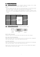
3 CABLE CONNECTION 3.1 Before Connecting Before connecting your monitor to the computer, change the display screen settings (Resolution and frequency) in accordance with the charts below. Note: - The lower display modes like 640x 480, automatically enlarge to the maximum display mode (1600x 1200), and some lines of the characters may become fuzzy.
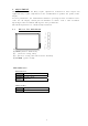
4. ADJUSTMENT This touchmonitor will not likely require adjustment. Variations in video output and application may require adjustments to the touchmonitor to optimize the quality of the display. For best performance, the touchmonitor should be operating in native resolution 1600 x 1200. Use the Display control panel in Windows to choose 1600 x 1200 resolution. Operating in other resolutions will degrade video performance. All control adjustments are automatically memorized. 4.
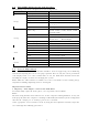
4.2 OSD MENU Adjustments and Settings The following table shows all adjustment and setting menus. Main Menu Input Image Sub Menu Reference Main Input VGA / DVI Brightness 50 Contrast 50 Sharpness 12 Aspect Ratio Full / Full Aspect / Native / User / 5:4 / 4:3 Mode Select Overlap selection Color temp 5500K, 6500K, 7500K, 8500K, 9300K, 10000K, USER Setup Gamma 3.0, 2.8, 2.6, 2.4, 2.2, 2.0, 1.
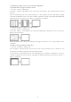
2. Adjust by using menu in the OSD Menu. (1) Vertical bars appear on the screen → Use the adjustment. Select the and eliminate the vertical bars by using the UP and Down of the Control buttons. Do not continuously press the Control buttons, as the adjustment value will change quickly and make it difficult to locate the most suitable adjustment point. If the horizontal flickering, blur or bars appear, proceed to adjustment as follows. (2) Horizontal bars appear on the screen.
5. TROUBLESHOOTING If a problem persists even after applying the suggested remedies, contact a dealer. Problems Points to check with Possible Solutions Check that the power cord is correctly connected. If the problem persists, turn off the monitor power for a few minutes, then turn it back on and try again. - when the signal is not inputted correctly, even if the monitor 1. No picture Indicator status: Off functions properly.
6. CLEANING Periodic cleaning is recommended to keep the monitor looking new and to prolong its operation lifetime. Note: Never use thinner, benzene, alcohol (ethanol, methanol, or isopropyl alcohol), abrasive cleaners, or other strong solvents, as these may cause damage to the cabinet or LCD panel. Cabinet To remove stains, wipe the cabinet with a soft, lightly moistened cloth using a mild detergent. Do not spray wax or cleaner directly into the cabinet. (For details, refer to the manual of the PC.
7. SPECIFICATION 7.1 Specification Display characteristics Size: 20.1″ Supported Color : 16.7M colors Native resolution: 1600×1200 Active Area: 408 x 306 mm Aspect Ratio: 4:3 Pixel Pitch : 0.255 x 0.255 mm Viewing angle: (8 Bit) 178° V/H @ contrast ratio > 10 Brightness: 250 cd/m2 Contrast ratio: 800:1 Typ. Lamp Life Time: Min. 50,000 Hr Response Time TrR: 7ms Typ. VESA DDC : DDC 2B compliant ; TrD: 9ms Typ.
7.2 D-Sub 15pin Connector Pin Signal Pin Signal Pin Signal 1 Red video 6 Red ground 11 Ground Shorted 2 Green video 7 Green ground 12 Data (SDA) 3 Blue video 8 Blue ground 13 H. Sync 4 Ground 9 No pin 14 V. Sync 5 No pin 10 Ground Shorted 15 Clock (SCL) 7.3.
7.5 Preset Timing Timing Dot Clock Signal Polarity Frequency MHz H V FH (kHz) FV (Hz) PC Mode 720×400 28.3 - - 31.5 70.0 VGA 640×480 25.2 - - 31.5 60.0 VESA 800×600 40.0 + + 37.9 60.0 VESA 1024×768 65.0 - - 48.4 60.0 VESA 1152×900 108.0 - - 71.8 76.0 VESA 1280×1024 108.0 + + 64.0 60.0 VESA 1600x1200 162.0 + + 75.0 60.0 VESA 1600x1200 202.0 + + 93.7 75.