S242P User Manual 1
S262P User Manual TABLE OF CONTENTS 1. SAFETY SYMBOLS & PRECAUTIONS ................................................................................................3 1.1 SAFETY SYMBOLS...............................................................................................................3 1.2 PRECAUTIONS ......................................................................................................................3 2. INTRODUCTION ..............................................................
S262P User Manual l SAFETY SYMBOLS & PRECAUTIONS l SAFETY SYMBOLS Medical displays are mainly used to provide trained medical staff with professional digital images, thus for the professional reading and analysis. This manual uses the safety symbols below. They denote critical information. Please read them carefully. WARNING Failure to abide by the information in a WARNING may result in serious injury and can be life threatening.
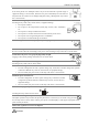
S262P User Manual Place the device on a solid and stable surface. If the unit is placed on an inadequate surface may occur fall and result in personal injury or equipment damage. If the unit falls, disconnect the power immediately and ask dealer for help. Please do not continue to use damaged equipment. Using a damaged unit may result in fire or electric shock. Set the unit in an appropriate location. Not doing so may result in fire, electric shock, or equipment damage. l Do not place outdoors.
S262P User Manual Handle with care when carrying the unit. Disconnect the power cord and signal cables and remove the optional unit. Moving the unit with the cord or the option attached is dangerous. It may result in injury. When handling the unit, grip the bottom of the unit firmly with both hands ensuring the panel faces outward before lifting. Dropping the unit may result in injury or equipment damage. Do not block the ventilation slots on the cabinet. l Do not place any objects on the ventilation slots.
S262P User Manual FCC Warning: This device complies with Part 15 of the FCC Rules. Operation is subject to the following two conditions: (1) this device may not cause harmful interference, and (2) this device must accept any interference received, including interference that may cause undesired operation. Changes or modifications not expressly approved by the party responsible for compliance could void the user's authority to operate the equipment.
S262P User Manual l INTRODUCTION S262P is a professional full HD surgery medical image display used in the operating room with the characteristic such as high definition and high brightness. This product is with precise calibration and completely compliant with standard of medical imaging, it uses the latest generation of LED backlight panel, supports resolution 1920 x1080, provides HD display for the output of surgery, endoscope and etc.
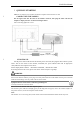
S242P User Manual l QUICKLY STARTING Note: Be sure that the power switches of both the computer and the monitor are OFF. l CONNECTING THE CABLES Put the signal cable into the back of the monitor connector, then plug the other end into the computer's display interface. As shown in the figure below. After connecting, tighten the screws. l STARTING UP Put the power cord into the back of the monitor power connector, then plug the other end into a power outlet.
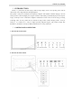
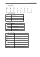
S242P User Manual l OSD MENU l SIGNAL INDICATOR Color Display mode Blue Operating mode Orange Standby mode None Power off mode l SHORTCUTS Key l Function Left Reduce brightness values Right Increase brightness values Up Reduce contrast values Down Increase contrast values KEY FUNCTION Keys Function Signal switching Menu/Confirm Signal switching Enable the menu and moved to the next entry column/confirm the choice EXIT Exit menu/Automatic adjust displays Left Move to the left c
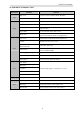
S262P User Manual 4.1 OSD MENU INTRODUCTION Main Menu Sub Menu Reference Main Input VGA/DVI /CVBS /S-VIDEO/YPbPr/ RGB/SDI PIP Mode Large pip, Side-by-side, Off Brightness Brightness adjust Contrast Contrast adjust Sharpness Sharpness adjust Aspect Ratio 5:4/ 4:3/ Full/ Full Aspect/ Native/ User Input Image Mode Select signal to select different suitable overlapping mode. Color Temp 5500K/6500K/7500K/8500K/9300K/10000K/User Gamma DICOM/ 2.4/2.3/2.2/ 2.1/ 2.0/ 1.
S242P User Manual l TROUBLESHOOTING If a problem persists even after applying the suggested remedies, contact a dealer. Problems Points to check with Possible Solutions Check that the power cord is correctly connected. If the problem persists, 1. No picture Indicator status: Off turn off the monitor power for a few minutes, then turn it back on and try again. Indicator status: Green Check the shortcut key setting.
S242P User Manual l CLEANING Periodic cleaning is recommended to keep the outlook of monitor clean and prolong the life time. Note: Never use thinner, benzene, alcohol (ethanol, methanol or isopropyl alcohol), abrasive cleaners or other solvents before the solubility, as they may damage the cabinet or LCD screen. Cabinet To remove stains, use a soft cloth lightly moistened with a mild detergent solution. Do not spray wax or cleaner directly into the cabinet. (For details, refer to the manual of the PC.
S242P User Manual l PRODUCT PACKAGING AND ACCESSORIES LCD monitor Power cable DVI signal cable BNC signal cable S-VIDEO signal cable User manual Power adapter 13
S262P User Manual l SPECIFICATION 8.1 SPECIFICATION LCD panel 26” TFT color LCD, AG, Hard coating Brightness(Typ.) 450 cd/m2 Contrast 1400:1 response speed 8ms Viewing angle Horizontal&Vertical:178°at Φ=0°,90°,180°,270° CR >10 Pixel pitch 0.300 mm x 0.300 mm Horizontal 31~80 kHz scanning frequency Vertical 50~76 Hz scanning frequency Resolution 1920 x 1080 Support color 1.07 Billion Power supply DC:24V(4.2A) Power consumption Max:55 W Input interface VGA 15 pin D-sub,0.
S242P User Manual 8.2 D-SUB 15 PIN CONNECTOR Pin Signal Pin Signal Pin Signal 1 Red video 6 Red ground 11 Ground Shorted 2 Green video 7 Green ground 12 Data (SDA) 3 Blue video 8 Blue ground 13 H. Sync 4 Ground 9 5V 14 V. Sync 5 GND 10 Ground Shorted 15 Clock (SCL) 8.
S262P User Manual 8.6 YPbPr/RGB CONNECTOR Y/G Pb/B Pr/R Pin Signal 1 Y/G Pb/B Pr/R 2 GND GND GND 8.7 PRESET TIMING l VGA/DVI preset timing Video Formats Horizontal Frequency (kHz) Vertical Frequency (Hz) Pixel Clock (MHz) 720 x 400 31.5 70.1 28.3 640 x 480 800 x 600 31.5 37.9 59.9 60.3 25.2 40.0 1024 x 768 1280 x 1024 1600 x 1200 1920 x 1080 48.4 64.0 75.0 66.6 60.0 60.0 60.0 59.9 65.0 108.0 162.0 138.50 1920 x 1080 67.0 60.0 172.
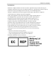
S262P User Manual l SDI input preset timing Video Formats Horizontal Frequency (kHz) Vertical Frequency (Hz) Pixel Clock (MHz) 480i/60Hz 15.734 59.940 13.50 576i/50Hz 720p/50Hz 15.625 37.50 50.0 50.0 13.50 74.250 720p/60Hz 45.00 60.0 74.250 1080i/50Hz 1080i/60Hz 28.125 33.750 50.0 60.0 74.250 74.250 l DECLARATION OF CONFORMITY This equipment is in conformity with the provisions of the CCC, CE, IEC60601-1 standard.