
User's Manual


B‐LINKELECTRONICCO.,LTDinshenzhen
9
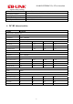
11:Packing
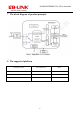
12:The 6
th
Pin connect to antenna, please refer to design demand
Connect to the 6
th
pin of Module
Connect to the 5
th
pin of Module
a) The current of 3.3V power supply must be >300mA, its ripple wave must be <30mV. The GND
pins of module and external antenna need to be an incorporated part. The ground plane should be
larger, module and antenna should keep far away from interference source.
b) The sixth pin is 2.4G high frequency output, coplanar impedance of layout line between this pin
to antenna interface should be 50Ω, we suggest use arc line or straight line, and beside the line
there will be ground plane that its length as shout as possible, the longest length is no more than
50mm.
c) L1, C1, C2 constitute a π-type network that we preset, please make it close to antenna interface,
this π-type network is used to match the antenna parameters and control the radiation. It should
be adjusted according to the real condition when being used. Normally you can only mount L1
that its parameters are: 10pF, NP0 material. No need C1 and C2