
Product Info


DS-2472-01
<Rev.0.0> page 10/ 63
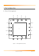
1.2. Device Pin Descriptions
Pin type abbreviation: A = Analog, D = Digital, P = Power, I = Input, O = Output
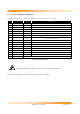
Table 1. Pin Descriptions
*
Caution
: ESD sensitive. Please refer to Section 2.5 for more information.
Note 1: Connecting bypass capacitor(s) to the pin as close as possible.
Pin Symbol Type Description
1 RF_P AIO Differential RF input/output (+)
2 RF_N AIO Differential RF input/output (-)
3 VDD_RF PI RF power supply
(1)
4 VDD_D PI Digital circuit power supply
5 GND Ground Ground
6 INT DO Interrupt pin to the micro-processor
7 SI/SIO DI/DIO Serial interface data input (SI: 4 wire SPI mode, SIO: 3-wire SPI mode)
8 SO DO Serial interface data output
9 SCLK DI Serial interface Clock
10 SEN DI Serial interface enable
11 RESETn DI Global hardware reset pin, active low
12 XTAL_N AI 16 MHz Crystal (-)
13 XTAL_P AI 16 MHz Crystal (+) (input for an external clock if needed)
14 VDD_PLL PI RF power supply
(1)
15 VDD_VCO PI VCO power supply
16 GND_PLL Ground Ground
17 IC Ground Pad Ground Backside ground plane. Must be connected to the ground.