
Product Specs
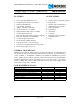
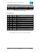
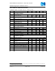


Table Of Contents
- FEATURESAPPLICATIONS
- GENERAL DESCRIPTION
- QUICK REFERENCE DATA
- PIN FUNCTIONS
- ELECTRICAL SPECIFICATIONS
- Package marking:
- Absolute Maximum Ratings
- Temperatures
- ATTENTION!
- Glossary of Terms
- FUNCTIONAL DESCRIPTION
- Pin functions in the different modes of nRF24L01
- Standby Modes
- Power Down Mode
- Packet Handling Methods
- ShockBurst™
- Enhanced ShockBurst™
- Enhanced ShockBurst™ Transmitting Payload:
- Enhanced ShockBurstTM Receive Payload:
- DEVICE CONFIGURATION
- SPI Interface
- SPI Instruction Set
- Interrupt
- SPI Timing
- Memory Map
- Configuration for compatibility with nRF24XX
- PACKET DESCRIPTION
- IMPORTANT TIMING DATA
- nRF24L01 Timing Information
- Enhanced ShockBurst™ timing
- PERIPHERAL RF INFORMATION
- Output Power adjustment
- Crystal Specification
- nRF24L01 sharing crystal with a micro controller.
- Crystal parameters:
- Input crystal amplitude & Current consumption
- PCB layout and de-coupling guidelines
- APPLICATION EXAMPLE
- DEFINITIONS
- LIFE SUPPORT APPLICATIONS
- YOUR NOTES
- 空白页面
- 空白页面
- 空白页面
- 空白页面

PRELIMINARY PRODUCT SPECIFICATION
nRF24L01 Single Chip 2.4 GHz Radio Transceiver
Nordic Semiconductor ASA - Vestre Rosten 81, N-7075 Tiller, Norway - Phone +4772898900 - Fax +4772898989
Page 11 of 38
Revision: 1.1
November 2005
Packet Handling Methods
nRF24L01 has the following Packet Handling Methods:
ShockBurst™ (compatible with nRF2401, nRF24E1, nRF2402 and nRF24E2
with 1Mbps data rate, see page 24)
Enhanced ShockBurst™
ShockBurst™
ShockBurst™ makes it possible to use the high data rate offered by nRF24L01
without the need of a costly, high-speed microcontroller (MCU) for data
processing/clock recovery. By placing all high speed signal processing related to RF
protocol on-chip, nRF24L01 offers the application microcontroller a simple SPI
compatible interface, the data rate is decided by the interface-speed the micro
controller itself sets up. By allowing the digital part of the application to run at low
speed, while maximizing the data rate on the RF link, ShockBurst™ reduces the
average current consumption in applications.
In ShockBurst™ RX, IRQ notifies the MCU when a valid address and payload is
received respectively. The MCU can then clock out the received payload from an
nRF24L01 RX FIFO.
In ShockBurst™ TX, nRF24L01 automatically generates preamble and CRC, see
Table 12. IRQ notifies the MCU that the transmission is completed. All together, this
means reduced memory demand in the MCU resulting in a low cost MCU, as well as
reduced software development time. nRF24L01 has a three level deep RX FIFO
(shared between 6 pipes) and a three level deep TX FIFO. The MCU can access the
FIFOs at any time, in power down mode, in standby modes, and during RF packet
transmission. This allows the slowest possible SPI interface compared to the average
datarate, and may enable usage of an MCU without hardware SPI.
Enhanced ShockBurst™
Enhanced ShockBurst™ is a packet handling method with functionality that makes bi-
directional link protocol implementation easier and more efficient. In a typical bi-
directional link, one will let the terminating part acknowledge received packets from
the originating part in order to make it possible to detect data loss. Data loss can then
be recovered by retransmission. The idea with Enhanced ShockBurst™ is to let
nRF24L01 handle both acknowledgement of received packets and retransmissions of
lost packets, without involvement from the microcontroller.