XT-ZB6 Product Specification ——Zigbee3.0 and BLE5.0 Coexistence Module Version: 1.0 Features General Date: June.23, 2022 Ethernet RMII interface Camera interface SPI * 1; EN * 1; PWM *5; 10-bit DAC ; 12-bit ADC; Chip: BL706C-22 Optional: 16M bit Flash, 16M bit pSRAM Module Size:16mm x 24mm x 3mm Bluetooth® Specification v5.0 Zigbee 3.0, Base Device Behavior, Core Stack R21, Green Power 2.
Update Record Date Version Update 2022-06-23 V1.
Table of Contents 1. Introduction ....................................................................................................................... 1 2. Interface Definition ........................................................................................................... 3 3. Size and Layout ................................................................................................................. 5 4. Electrical Characteristics ........................................................
XT-ZB6 User Manual 1. Introduction XT-ZB6 is highly integrated BLE and Zigbee combo module for IoT applications. XT-ZB6’s wireless subsystem contains 2.4G radio, BLE + Zigbee baseband and MAC designs. Microcontroller subsystem contains 32-bit RISC CPU, high-speed cache and memories. Power Management Unit controls ultra-low-power modes. Moreover, varieties of security features are supported. Peripheral interfaces include UART, PWM, USB, I2C, ADC, DAC and GPIOs. Fig.1.
XT-ZB6 User Manual Technical parameters for XT-ZB6 are listed as follows. Table 1.1 XT‐ZB6 Parameters Types Items Parameters Zigbee Sensitivity -104 dBm @250Kbps -104 dBm @120Kbps BLE Sensitivity RF -100 dBm @500Kbps -97 dBm @1Mbps -94 dBm @2Mbps TX Power 0-14 dBm TX EVM 11% Antenna PCB antenna / U.F.L IPEX V1 CPU 32-bit RISC CPU Interface UART/GPIO/PWM Working voltage 2.5V ~ 3.6V 3.
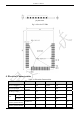
XT-ZB6 User Manual 2. Interface Definition XT-ZB6 module interface definition is shown as below。 Fig.2.1 XT-ZB6 Pin Definition Working mode and pins function are shown in Table 2.1. Table.2.1 Working mode Mode GPIO31 UART Download Mode High Flash Boot Mode LOW (default) Table.2.2 Pins Function Definition Num. Pin Name Type Function 1.28. 32.
XT-ZB6 User Manual 8 GPIO20 I/O SF1_IO3,PIX_DAT7,SCL,RMII_RXERR 9 GPIO21 I/O SF1_CLK,SDA,RMII_TX_EN 10 GPIO22 I/O SF1_IO2,SS,PWM_CH2,RMII_RX_DV 11 GPIO23 I/O SCLK, I2S_DI, SPI,SDA,PWM_CH3,IRTX 12 GPIO24 I/O SF2_IO1,PIX_DAT5,SCL,RMII_MDC 13 GPIO25 I/O MISO/MOSI,SDA,I2S_FS,PWM_CH0 14 GPIO26 I/O SF2_IO3,SS,PIX_DAT7,RMII_RXERR 15 GPIO29 I/O PIX_DAT5,PEM_CH4 16 GPIO28 I/O MISO/MOSI,SCL,I2S_BCLK,PWM_CH3,RMII_RX_DV 17 GPIO27 I/O SF2_CLK,SCLK, RMII_TX_EN 18 GPIO30 I/O PIX
XT-ZB6 User Manual 3. Size and Layout Shape for XT-ZB6 can be shown as follows. Fig.3.1 Shape for XT-ZB6 (a) Vertical View ShenZhen ThingsTurn Technology Co.
XT-ZB6 User Manual (b) Side View Fig.3.2 Size for XT-ZB6 Fig.3.3 PCB Layout for XT-ZB6 4. Electrical Characteristics Table 4.1 Electrical Characteristics Parameters Condition Min Classical Max Unit Store Temperature - -40 Normal 125 ℃ Sold Temperature IPC/JEDEC STD-020 - - 260 ℃ Working Voltage - 2.5 3.3 3.6 V VIL/VIH - -/2.0 - 0.8/- VOL/VOH - -/2.4 - 0.4/- TAMB=25℃ - - 2 KV TAMB=25℃ - - 0.
XT-ZB6 User Manual 5. Power Consumption Table 5.1 Power Consumption Parameters Min Classical Max Unit RX only - 3.5 - mA TX 0dbm - 4.8 - mA TX 10dbm - 17 - mA TX 14dbm - 45 - mA Run in RAM @RC32M 144MHz - 8.44 - mA Run in RAM @RC32M 32MHz - 3.36 - mA Run in FLASH @RC32M 144MHz - 7.72 - mA Run in FLASH @RC32M 32MHz - 3.39 - mA Hibernate Mode - 1.2 - uA Shut Down - 0.1 0 uA 6.
XT-ZB6 User Manual 7. Recommended Reflow Profile (1) Reflow Times <= 2 times (Max.) (2) Max Rising Slope: 3℃/sec (3) Max Falling Slope: -3℃/sec (4) Over 217℃ Time: 60~120sec (5) Peak Temp:240℃~250℃ Fig.7.1 Recommended Reflow Profile 8. Minimum User System This module can work just at 3.3V working voltage: Fig.8.1 Minimum User System Note: ShenZhen ThingsTurn Technology Co.
XT-ZB6 User Manual (1) The working voltage for module is DC 3.3V; (2) The max current from IO of this module is 12mA; (3) Zigbee module is at download mode: GPIO31 are HIGH level, then module reset to power on; (4) Zigbee module is connected to RXD of the other MCU, and TXD is connected to RXD of the other MCU. 9. Recommended Layout Design XT-ZB6 Wi-Fi module can be sold on PCB board directly. For the high RF performance for the device, please notice the placement of the module.
XT-ZB6 User Manual Fig.9.2 Solution 2 Fig.9.3 Solution 3 10. Peripheral Design Suggestion XT-ZB6 module is already integrated into high-speed GPIO and Peripheral interface, which may be generated the switch noise. If there is a high request for the power consumption and EMI characteristics, it is suggested to connect a serial 10~100 ohm resistance, which can suppress overshoot when switching power supply, and can smooth signal. At the same time, it also can prevent electrostatic discharge (ESD). 11.
XT-ZB6 User Manual • Charged-device model (CDM): ±500 V 12. U.F.L RF Connector XT-ZB6-E module use U.F.L type RF connector for external antenna connection. (IPEX V1.0). Fig.12.1 U.F.L RF Connector 13. Packing Instruction The product is packed in a tray, as shown in the following figure. The size of the single box is: 340 x 360 x 60mm, and 800 pieces module is in the box. And the outer box size is 355 x 375 x 325mm, including 5 single box which include 4000 pieces module.
XT-ZB6 User Manual Fig.13.1 Module Package ShenZhen ThingsTurn Technology Co.
XT-ZB6 User Manual FCC WARNING FCC Caution: Any changes or modifications not expressly Approved by the party responsible for compliance could void the user's authority to operate this equipment. This device complies with Part 15 of the FCC Rules. Operation is subject to the following two conditions: (1) This device may not cause harmful interference, and (2) this device must accept any interference received, including interference that may cause undesired operation.
XT-ZB6 User Manual 2.2 List of applicable FCC rules List the FCC rules that are applicable to the modular transmitter. These are the rules that specifically establish the bands of operation, the power, spurious emissions, and operating fundamental frequencies. DO NOT list compliance to unintentional-radiator rules (Part 15 Subpart B) since that is not a condition of a module grant that is extended to a host manufacturer. See also Section 2.
XT-ZB6 User Manual KDB Publication 996369 D02 FAQ – Modules for Micro-Strip Antennas and traces. The integration information shall include for the TCB review the integration instructions for the following aspects: layout of trace design, parts list (BOM), antenna, connectors, and isolation requirements. a) Information that includes permitted variances (e.g.
XT-ZB6 User Manual The module manufacturers shall provide a list of acceptable unique connectors. Explanation: The product antenna uses an irreplaceable antenna with a gain of 1dBi 2.8 Label and compliance information Grantees are responsible for the continued compliance of their modules to the FCC rules. This includes advising host product manufacturers that they need to provide a physical or e-label stating “Contains FCC ID” with their finished product.